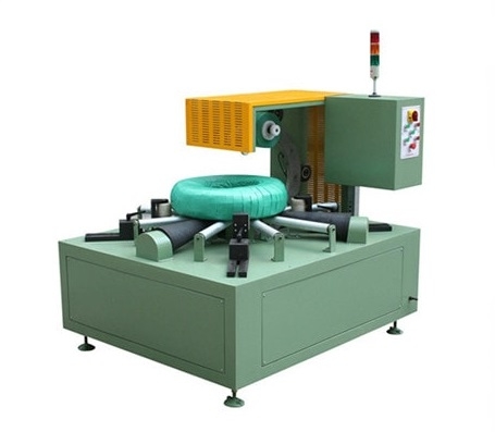
How Ring, Roller, and VFD Systems Improve Steel Coil Wrapping Machine Performance
Discover how drive systems affect steel coil wrapping machine operation. Explore the relationship between ring movement, rollers, motors, and VFD control, along with practical guidance on speed adjustment, system evaluation, and maintenance planning for consistent wrapping results.
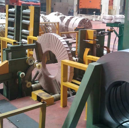
Ring, Roller, and VFD Drive Systems in Steel Coil Wrapping
Ring, Roller, and VFD Drive Systems in Steel Coil Wrapping
Ring, roller, motor, transmission, and variable-frequency drive (VFD) functions should be understood as one motion system. The ring guides the wrapping path; rollers support or rotate the coil where the configuration requires it; the drive train produces motion; and the VFD controls motor operation within the mechanical and control design limits.
A faster motor setting does not, by itself, prove a faster, stable, or acceptable package. The useful question is whether the complete motion path behaves as intended for the approved coil, material, process sequence, and acceptance condition.

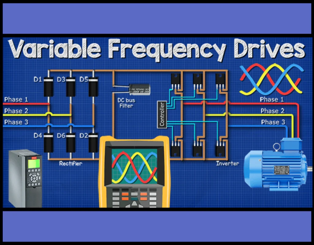
Follow the Motion Path Before Discussing a Setting
Start at the motor and follow the path to the moving element: motor, drive train, shaft or coupling, bearings, ring or roller, coil support, and material contact. Identify what is positively driven and what is free-running. This turns a vague "drive issue" into a reviewable chain of components and interfaces.
For a specific machine, the controlled drawing and electrical documentation must establish the actual architecture. A general article cannot infer gearbox type, roller arrangement, torque capacity, VFD parameters, or safety function from an equipment category name.
What the VFD Contributes—and What It Does Not
A VFD can be used to control motor speed and the way the motor accelerates or decelerates within the designed system. It may help establish repeatable operating behaviour, but it does not correct mechanical misalignment, worn support surfaces, an unsuitable package material, an overloaded structure, or an unreviewed safety design.
Keep these questions separate:
- What movement must occur at the ring or roller?
- Which component produces and transmits that movement?
- What parameter or sequence controls the motor behaviour?
- What evidence shows the result is acceptable for the approved coil and material?
That separation prevents a parameter change from being mistaken for a complete mechanical diagnosis.
Speed, Torque, Acceleration, and Synchronisation Are a System Question
Changes in coil mass, geometry, condition, friction, material path, acceleration, deceleration, and interaction with other stations can affect drive behaviour. Those factors do not justify copying a setting from another coil or machine. They justify a controlled review and, where needed, a defined test.
When a project needs a performance claim, record the configuration, coil, material, process boundary, method, repetitions, observations, acceptance criteria, and result. Without that record, language such as "higher torque," "smooth acceleration," or "stable synchronisation" remains a design intent or observation to verify, not a transferable fact.

Use Commissioning to Make the Motion Evidence Visible
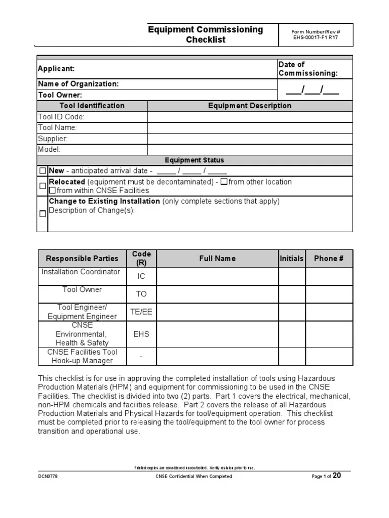
Commissioning is an opportunity to agree what must be observed, not a reason to rely on memory later. The project record should identify the approved normal condition, low-speed setup condition where applicable, controlled stop, restart sequence, and relevant abnormal states. Actual instructions must come from the model-specific documentation, risk assessment, and qualified project team.
The evidence record should identify the machine revision, coil and material, settings or recipe revision, observer, date, method, result, and any remaining limitation. This lets future maintenance distinguish a known baseline from an assumed baseline.
Maintenance Observations That Support a Useful Diagnosis
The maintenance plan should make it possible to compare like with like. Depending on the approved equipment documentation, this may include condition of roller surfaces, bearings, transmission, alignment, lubrication points, alarms, parameter backups, and recorded temperature or vibration observations.
Do not turn this list into a universal service instruction. The approved maintenance procedure, isolation method, competence requirements, and escalation route are specific to the installed equipment and site.
A Practical Next Step
Ask engineering for the controlled mechanical and electrical drawings, model/configuration identification, VFD parameter-backup policy, maintenance procedure, and commissioning record format. Then create one annotated motion-path review sheet that links each component to its evidence, owner, revision, and acceptance observation.
Visual Details
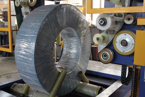
Click to enlarge

Click to enlarge
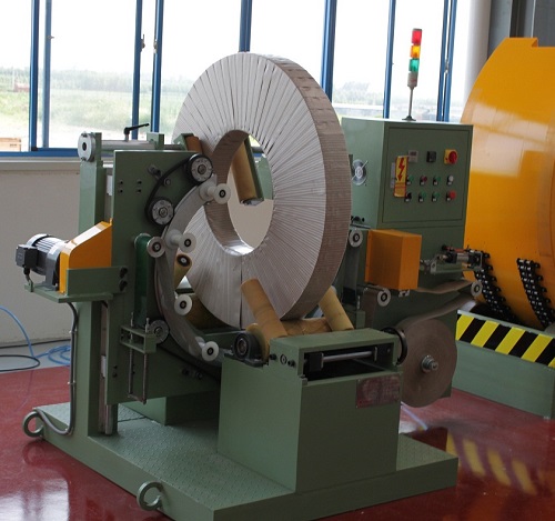
Click to enlarge
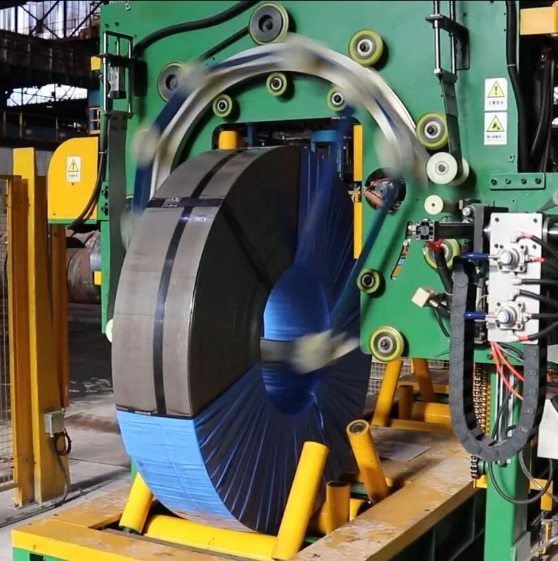
Click to enlarge
Watch How It Works
Discover how our automated packaging solutions optimize your production line efficiency. This video demonstrates the seamless operation designed for maximum protection.
Trusted by Steel Mills & Industry Leaders
Global manufacturers rely on FHOPE heavy duty packaging equipment


Ready to optimize your packaging line?
Get a custom quote with ROI analysis. Our engineers respond within 24 hours.
- Free layout design
- Global installation support
- 2-year warranty included
Your information is secure and will never be shared.
Related Machines
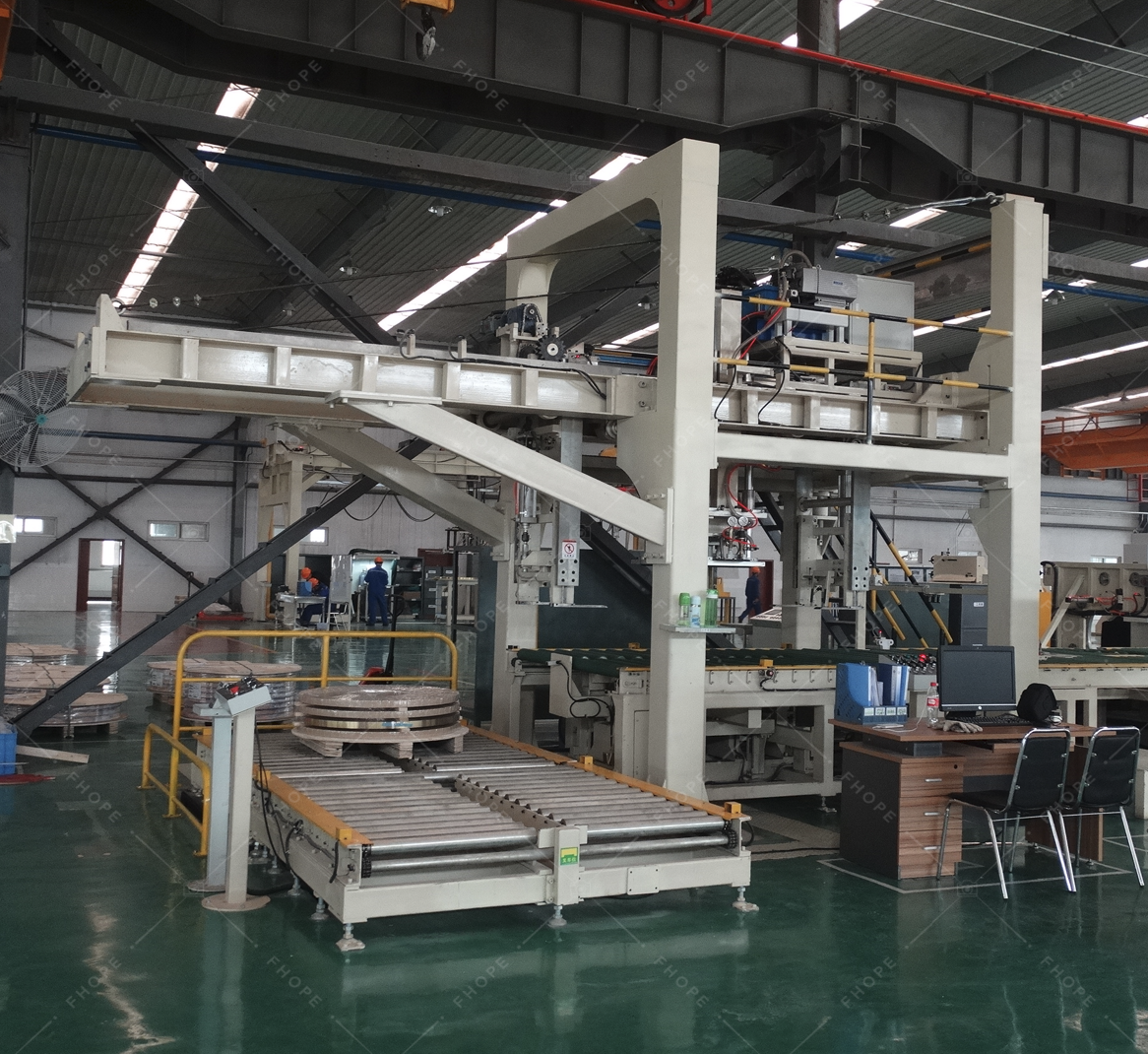
Steel Coil Packaging line
View Details →
Vertical coil packaging line
View Details →
Hose Coil Packaging line
View Details →
Copper Coil Packaging line
View Details →
Wire Coil Packaging line
View Details →
Panel Packaging line
View Details →
Pipe Bagging Machine
View Details →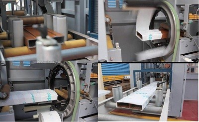
Aluminum profile packing line
View Details →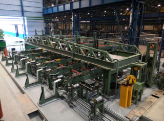
FHOPE Automatic pipe tube bundling&strapping line
View Details →
Automatic pipe tube bundling & strapping line
View Details →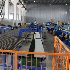
Automatic steel tube strapping machine
View Details →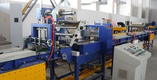
FHOPE Automatic steel tube packing machine
View Details →
Automatic plastic Pipe strapping packing line
View Details →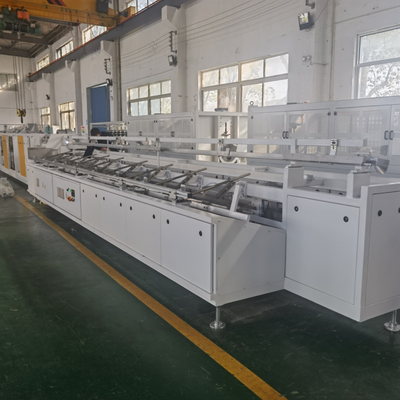
Automatic PPR/PVC Pipe bagging line
View Details →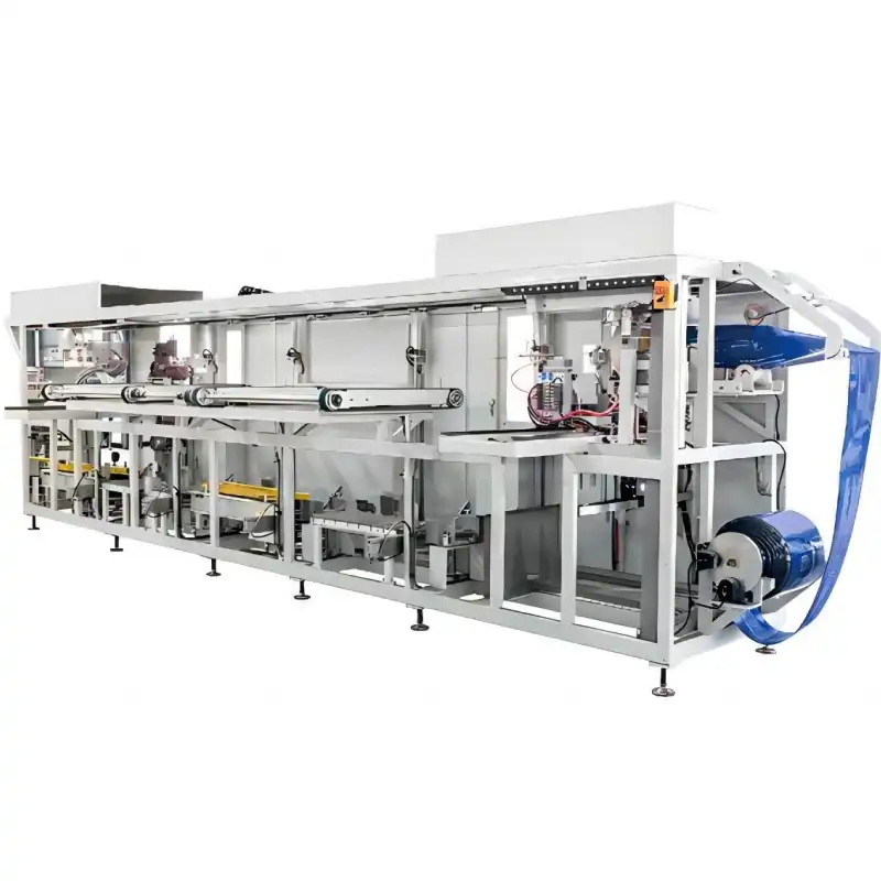
Platsic pipe bag packing machine
View Details →
Tyre Packing Machine FPT-200
View Details →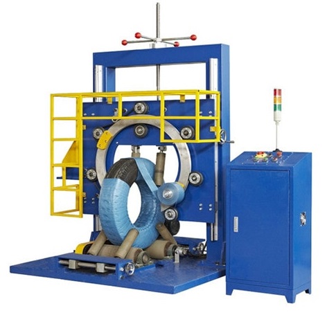
Tyre Packing Machine FPT-300
View Details →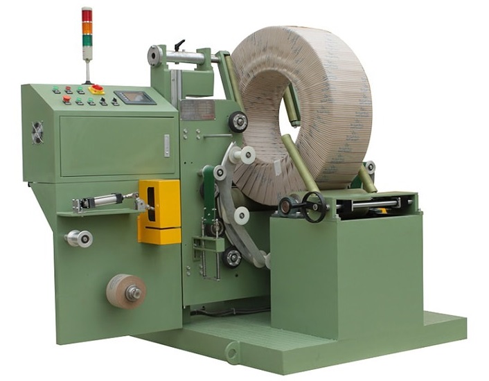
Tyre Packing Machine FPT-400
View Details →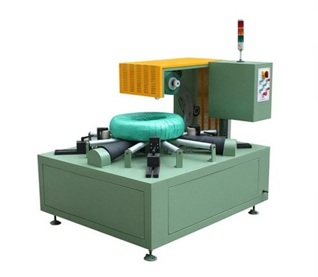
Cable Coil Packing Machine-FPCA100
View Details →