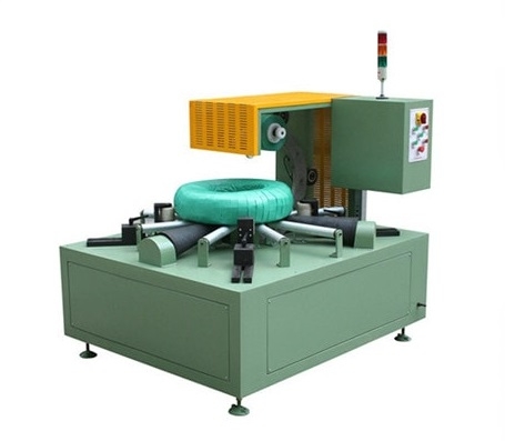
How Does a Steel Coil Wrapping Machine Work? A Step-by-Step Process Guide
A steel coil wrapping machine involves more than a rotating ring. Learn how loading, positioning, wrapping movement, material control, and finishing steps work together to create a consistent coil package while improving handling efficiency and reducing manual packaging challenges.

How Does a Steel Coil Wrapping Machine Work?
How Does a Steel Coil Wrapping Machine Work?
A steel coil wrapping machine coordinates a sequence: the coil is brought to a defined position, wrapping material is introduced through the coil eye, controlled relative movement lays material around the coil, the tail is secured, and the coil is handed to the next approved step. The exact components, motion order, safety functions, and recovery steps depend on the approved model documentation and site risk assessment.
The practical question is not simply "Does the ring rotate?" It is whether each handoff—from loading to outfeed—has a known condition for proceeding, a responsible person or system, and an accepted result.
This sequence explains one documented configuration; model, coil, material, settings, and timing conditions must be visible.
First, See the Entire Cycle as Seven Handoffs
The word wrapping can hide important work before and after the visible rotation. A complete cycle has at least these questions:
- Arrival: Has the coil reached the station by an approved transfer method?
- Positioning: Is it supported, oriented, and located within the current machine's approved envelope?
- Material introduction: Is the wrapping material on the intended path and is its leading end secured by the approved method?
- Controlled wrapping movement: Are the required motion and safety conditions present before movement begins?
- Completion: Has the agreed coverage or programmed completion condition been reached?
- Finish: Has the tail been secured and the packaging result checked?
- Handoff: Is the area safe and is the coil released to the next defined process step?
This article follows that order because it is the order an operator, engineer, or buyer needs to understand. It does not replace the site procedure for any one station.
How the Wrapping Cycle Unfolds
Step 1: Load and Position the Coil
The coil may arrive by crane, trolley, conveyor, or a line interface. The hardware that supports and centers it may include rollers, stops, guides, sensors, or another approved arrangement. Before wrapping motion is allowed, the machine's actual logic may require a presence signal, position confirmation, guard status, or other conditions.
Position matters because the material path and moving parts are designed for a known coil envelope. A shifted or incorrectly oriented coil can change coverage, create an unintended contact, or make the next handoff unreliable. The allowable location and response to a deviation must come from the current drawing, controls description, and risk review—not from a generic video.
Step 2: Introduce and Secure the Wrapping Material
The material travels from a roll or dispenser toward the wrapping path. In some designs, guides and actuators place and hold it; in others, an operator performs an approved threading or attachment step before the automatic portion begins. The product-family knowledge base lists several material families:
- Stretch film
- VCI film or paper
- PVC / opaque film
- Fabric
- Paper
It does not establish which is suitable for a specific coil, environment, or packaging requirement.
State the human-machine boundary plainly. A machine can automate the wrapping motion while material loading, changeover, or final inspection remains manual. That is not automatically a defect; it is a design and risk-control decision that should be visible in the work instruction and layout.
Step 3: Create the Wrapping Path with Relative Movement
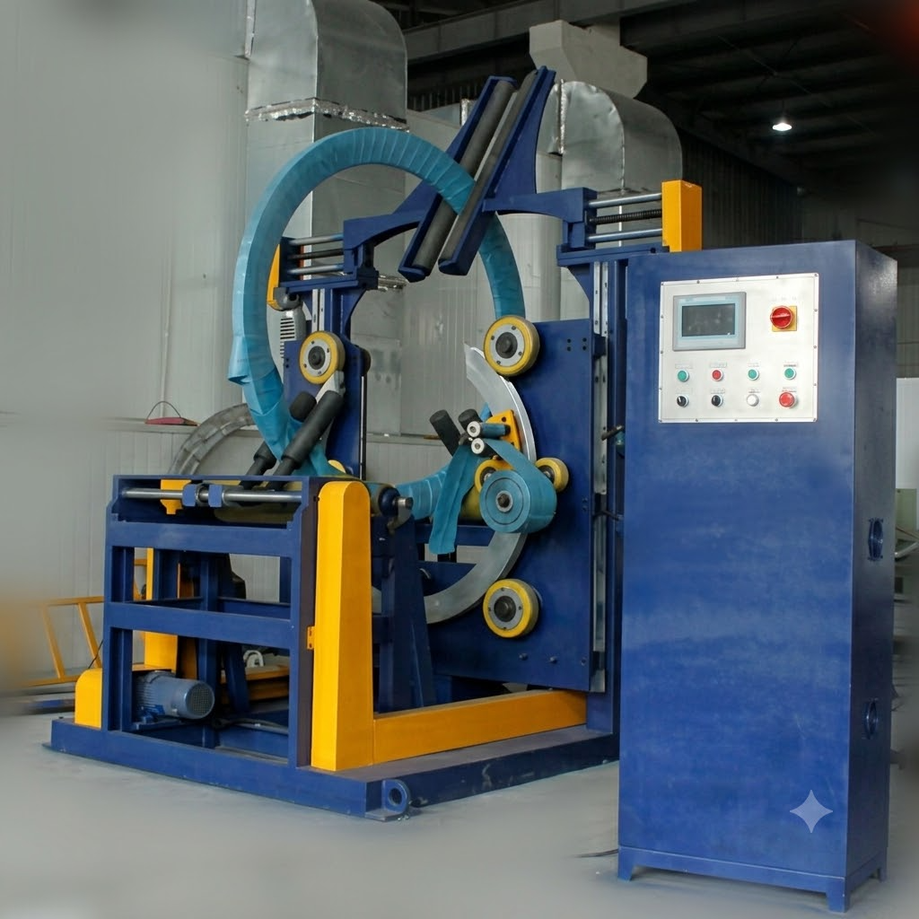
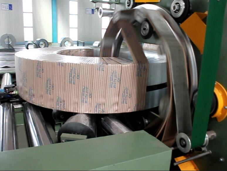
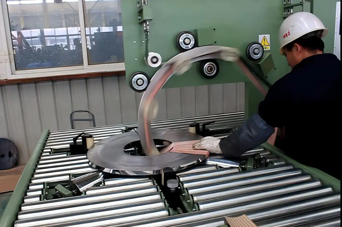
In an eye-through process, the material passes through the opening in the coil. A wrapping ring or assembly moves around that opening while the coil may be supported or moved by rollers. The relationship between those movements advances the material across the intended surface and produces an overlapping path.
The names of the motions are less important than the result: the material must follow the approved path without an unintended gap, snag, loose tail, or contact with a protected area. Different machines may achieve that through different mechanical arrangements, so a public diagram must match the shown equipment or be labelled as a generic explanation.

Step 4: Control Coverage Without Mistaking a Setting for a Result
Tension helps keep material in contact with the coil; overlap describes how one pass relates to the previous pass. Both affect the appearance and continuity of the package, but neither alone proves protection or package acceptance. Material type, surface condition, coil geometry, exposure route, handling, and inspection method all matter.
For a real packaging trial, record the following—and keep "specified," "measured," and "recommended" separate:
| What to Record | Why It Matters |
|---|---|
| Material specification | Different material families behave and protect differently |
| Setting or recipe version | Results must be reproducible against a known configuration |
| Coil condition and dimensions | Coverage depends on the actual coil envelope and surface |
| Coverage requirement | Defines the acceptance target, not just the machine setting |
| Inspection method | Acceptance must be checkable by an agreed procedure |
| Result | Turns the trial into a traceable quality record |
Do not publish an apparently precise overlap percentage or tension value without the current model record and quality basis.
Step 5: Determine When the Wrap Is Complete
Completion may be based on programmed turns, travel, position, or another approved condition. But "the motor stopped" is not a packaging acceptance criterion. The package still needs the defined coverage, secured tail, and inspection outcome for the particular job.
This is where a production line benefits from clear ownership: control logic may determine that motion is complete; a quality rule may determine whether the result is acceptable; the next station may require an additional release signal. Mixing these decisions into one vague "automatic" claim hides risks.
Step 6: Clamp, Cut, and Secure the Tail
At the end of the cycle, a machine may clamp the material, cut it, and secure the tail through a design-specific method. Other systems may require an operator-assisted finishing step. Do not generalize the mechanism from another model or describe a heat, pressure, adhesive, or clamp method unless it is documented for the selected configuration.
The useful inspection question is simple: can the responsible team show where the finished tail should be, how it is checked, what a defect looks like, and what happens when it is not acceptable? That turns an opaque mechanism into a controlled acceptance point.
Step 7: Unload, Reset, and Hand Off the Coil
After the package is accepted and the station's ready conditions are met, the coil moves to the next handling step. A recipe may be selected by an operator or through a connected system, but this article does not assume how that choice is made. The next cycle should begin only after the actual machine's defined conditions for safe readiness are met.
If the surrounding process needs strapping, labeling, weighing, stacking, or ERP/MES records, those are adjacent modules or interfaces unless they are explicitly included and tested as part of the quoted scope.
What the Controls Must Make Visible
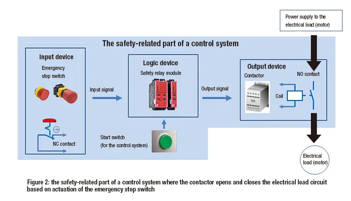
For a particular installation, the PLC/HMI is the place where machine state, permissives, selected recipe, motion status, and faults may be presented. A useful engineering review asks for a simple sequence diagram rather than relying on an attractive screen photo. It should identify what signal or condition permits the next action, which system owns it, and what stops the sequence.
Safety functions require the machine-specific risk assessment, documentation, and qualified review. This overview must never be used to bypass a guard, override an interlock, or authorise a restart.
When the Normal Cycle Is Interrupted
Common interruptions include:
- Material break or exhausted roll
- Opened guard
- Coil shift
- Loss of a required signal
- Power event
These are not merely nuisances—they change the operating state. The approved response is model- and site-specific. As a general boundary, stop motion as designed, prevent unexpected restart, keep the load stable, follow the approved isolation/recovery process, inspect the partial result, and escalate when the procedure requires it.
How to Verify the Cycle Before Calling It Production-Ready
Use a timed, documented trial—not the fastest single demonstration. Define the timing start and stop points, record repeated cycles, identify interruptions, and keep the coil, material, settings, and inspection method with the record. Capture both the normal path and the approved response to realistic interruptions only where safe to test under the responsible procedure.
The useful output is not just an average time. It is a traceable record that lets production, quality, engineering, and the supplier see what was included, what varied, and what must be improved.
Recommended Next Step
Request these three items for the exact machine under consideration:
- A current motion-sequence diagram
- A representative continuous-cycle video
- The approved interruption/recovery procedure
Review them with the coil envelope, material specification, acceptance criteria, and site handling plan in the same meeting. That is the point at which a general explanation becomes an implementable operating plan.
Visual Details

Click to enlarge
Click to enlarge
Click to enlarge
Click to enlarge
Watch How It Works
Discover how our automated packaging solutions optimize your production line efficiency. This video demonstrates the seamless operation designed for maximum protection.
Trusted by Steel Mills & Industry Leaders
Global manufacturers rely on FHOPE heavy duty packaging equipment


Ready to optimize your packaging line?
Get a custom quote with ROI analysis. Our engineers respond within 24 hours.
- Free layout design
- Global installation support
- 2-year warranty included
Your information is secure and will never be shared.
Related Machines
Steel Coil Packaging line
View Details →
Vertical coil packaging line
View Details →
Hose Coil Packaging line
View Details →
Copper Coil Packaging line
View Details →
Wire Coil Packaging line
View Details →
Panel Packaging line
View Details →
Pipe Bagging Machine
View Details →
Aluminum profile packing line
View Details →
FHOPE Automatic pipe tube bundling&strapping line
View Details →
Automatic pipe tube bundling & strapping line
View Details →
Automatic steel tube strapping machine
View Details →
FHOPE Automatic steel tube packing machine
View Details →
Automatic plastic Pipe strapping packing line
View Details →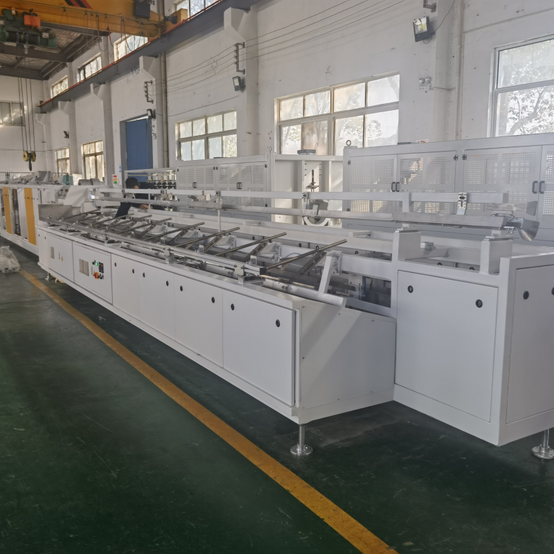
Automatic PPR/PVC Pipe bagging line
View Details →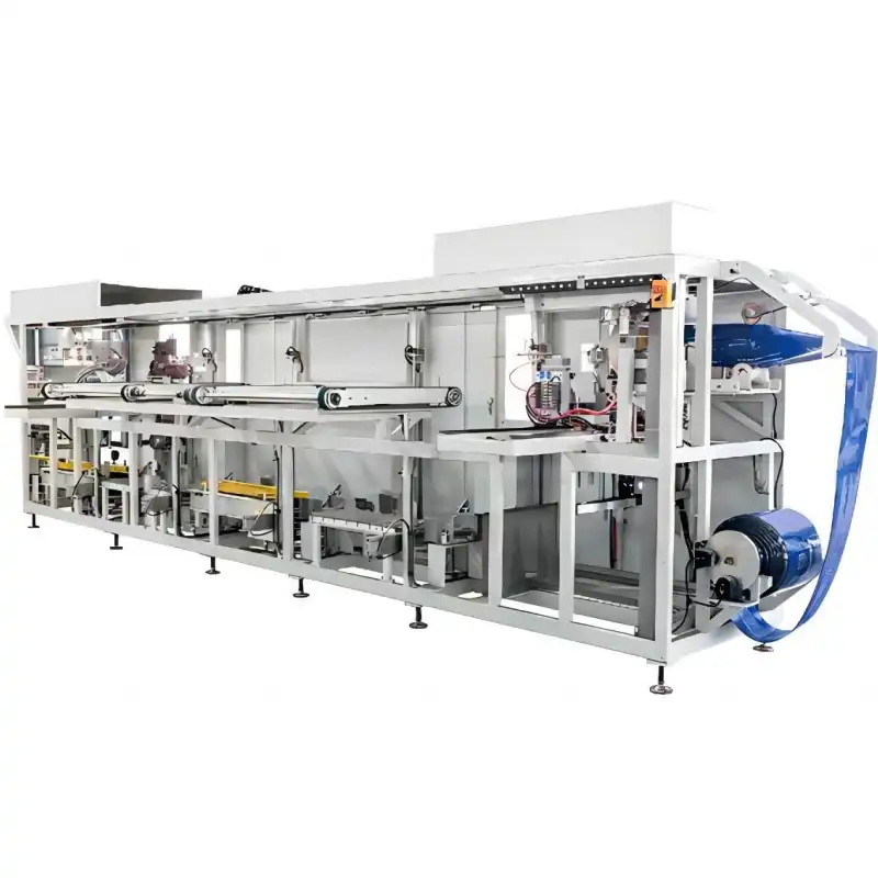
Platsic pipe bag packing machine
View Details →
Tyre Packing Machine FPT-200
View Details →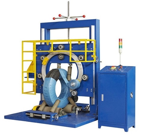
Tyre Packing Machine FPT-300
View Details →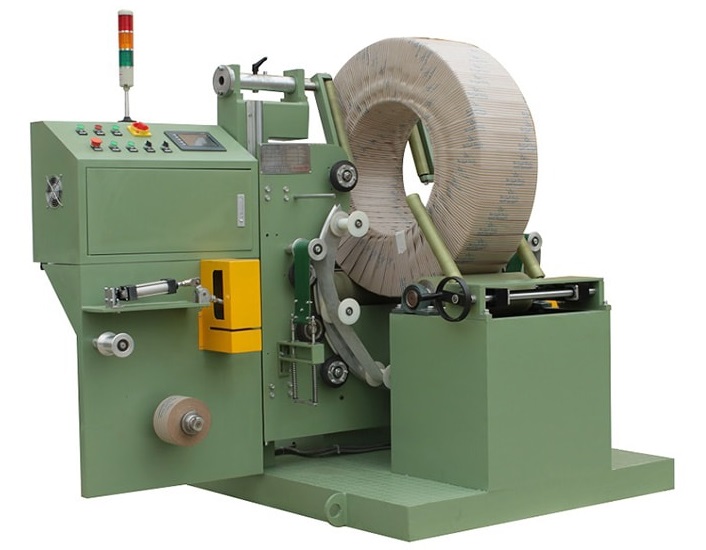
Tyre Packing Machine FPT-400
View Details →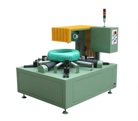
Cable Coil Packing Machine-FPCA100
View Details →