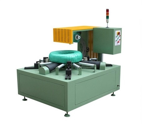
Coil Upender Integration for Steel Wrapping Lines: Design Orientation & Interfaces First
A coil upender changes orientation, but it is not automatically needed in every wrapping line. Map arrival, wrapping and dispatch orientations first, then design support surfaces, transfer interfaces, clearance and safety boundaries before selecting the motion.

How a Coil Upender Integrates With a Steel Coil Wrapping Line
How a Coil Upender Integrates With a Steel Coil Wrapping Line
An upender changes a coil's orientation. In a wrapping line, that single motion changes every adjacent interface: support surfaces, transfer direction, clearance, package protection, signals and safety boundary. The useful design question is not "Do we need an upender?" but "At which point must the coil change orientation, and what must be true before and after that turn?"
Begin with the Required Orientation
Map the coil's arrival orientation, the orientation required by the wrapper, and the orientation required at storage or dispatch. Some lines need a turn before wrapping; others after wrapping; others do not need one at all. Do not assume that a coil wrapper and an upender always belong in the same line.
The internal product knowledge identifies upender, tilter, tipper and turner as related naming terms for orientation-changing equipment. It does not establish the correct integration point, permitted coil range or safety design for a particular project.

Design the Interfaces Before Selecting the Motion
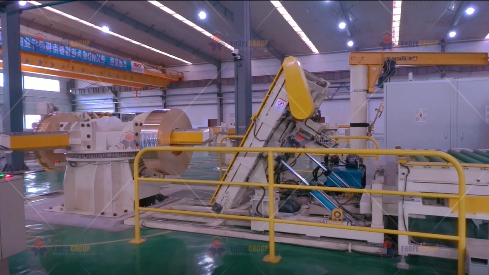
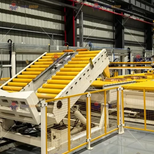
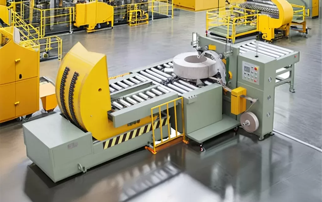
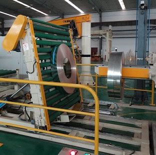
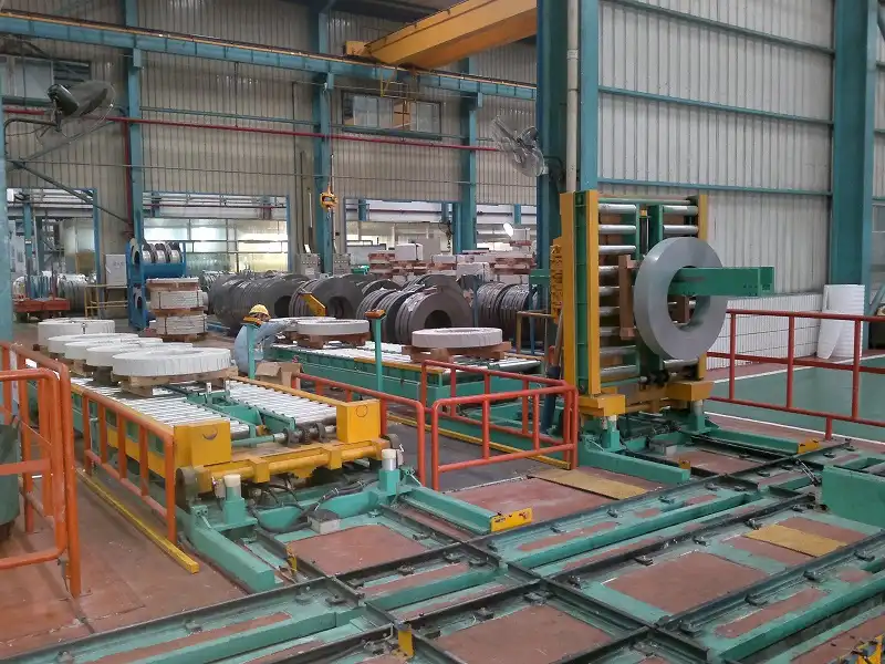
An integrated design defines how the coil enters, where it is supported during the turn, how it leaves, and how the next station accepts it. Verify height, centreline, clearance, contact surfaces and the condition that prevents motion when the coil is not correctly positioned. The wrapper opening and its support arrangement are part of this interface, not a later installation detail.
Protect Both the Coil and the Finished Package
If orientation changes after wrapping, assess every contact point against the actual packaging materials, edge protection, labels and acceptance criteria. A visually intact package is not proof that it remains acceptable after the turn. Use representative samples and an approved inspection method.
Treat Sequence and Safety as One System
The operating sequence needs explicit readiness and completion conditions for upstream equipment, the upender, the wrapper and downstream handling. It must also state the approved response to an occupied safety zone, a downstream block, incomplete movement or loss of power. The risk assessment and controlled procedure define safeguards and recovery; this page does not.
Public lifting guidance can inform general planning where lifting equipment is involved, but it does not certify an upender or replace a machine-specific risk assessment, local legal review or manufacturer instructions.
Measure the Line Impact Instead of Assuming It
The upender's time can be a serial delay, overlap with another station, or become a bottleneck. Determine this with the complete line sequence, product mix, buffer rules and exception cases. Do not claim capacity improvement without an agreed timing method and results.

A Practical Next Step
Freeze the orientation map and interface table before purchase. The FAT/SAT plan should then test representative coil conditions, positioning, normal transfer, downstream blockage, interruption, restart boundary and package inspection after the selected sequence.
Visual Details
Click to enlarge
Click to enlarge
Click to enlarge
Click to enlarge
Watch How It Works
Discover how our automated packaging solutions optimize your production line efficiency. This video demonstrates the seamless operation designed for maximum protection.
Trusted by Steel Mills & Industry Leaders
Global manufacturers rely on FHOPE heavy duty packaging equipment


Ready to optimize your packaging line?
Get a custom quote with ROI analysis. Our engineers respond within 24 hours.
- Free layout design
- Global installation support
- 2-year warranty included
Your information is secure and will never be shared.
Related Machines
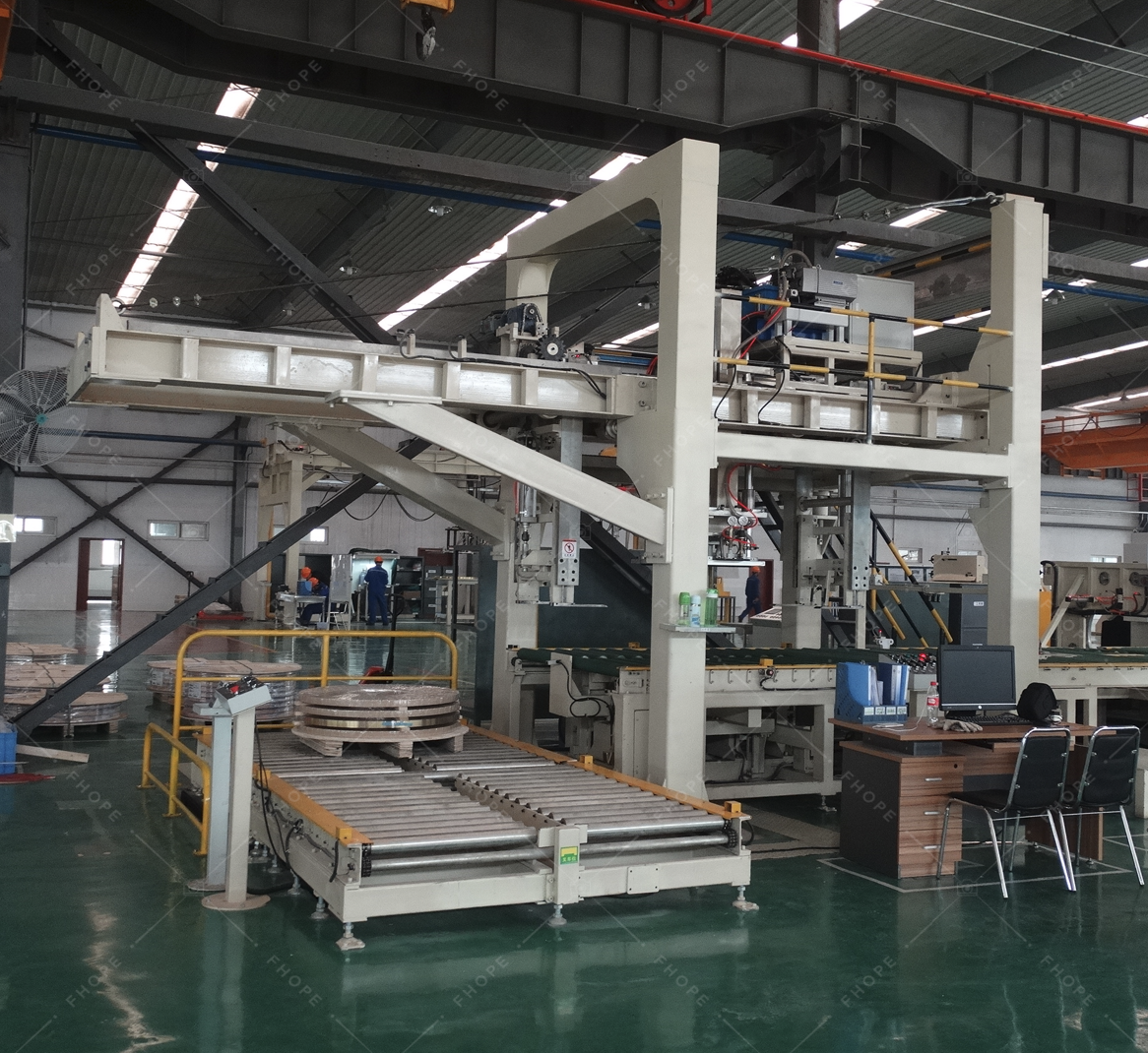
Steel Coil Packaging line
View Details →
Vertical coil packaging line
View Details →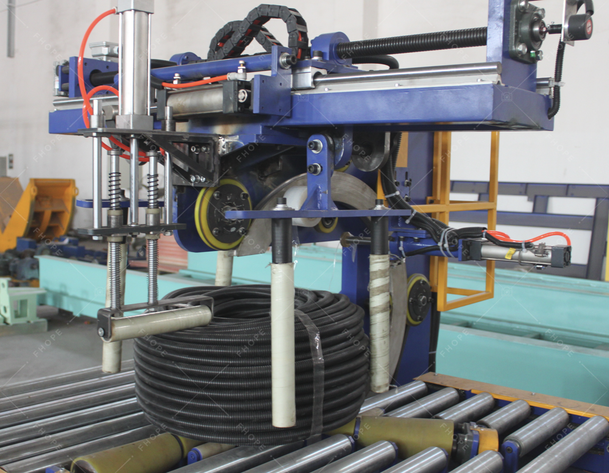
Hose Coil Packaging line
View Details →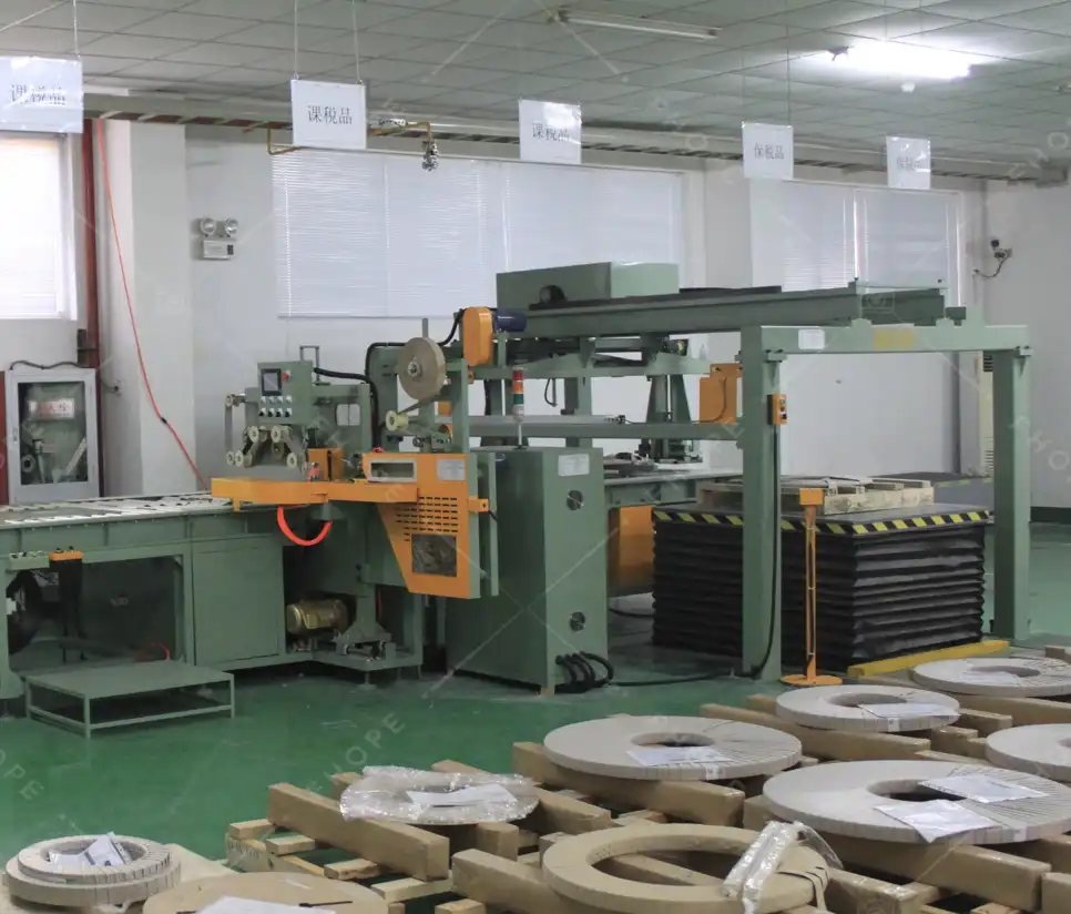
Copper Coil Packaging line
View Details →
Wire Coil Packaging line
View Details →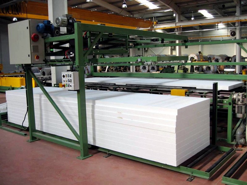
Panel Packaging line
View Details →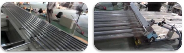
Pipe Bagging Machine
View Details →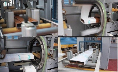
Aluminum profile packing line
View Details →
FHOPE Automatic pipe tube bundling&strapping line
View Details →
Automatic pipe tube bundling & strapping line
View Details →
Automatic steel tube strapping machine
View Details →
FHOPE Automatic steel tube packing machine
View Details →
Automatic plastic Pipe strapping packing line
View Details →
Automatic PPR/PVC Pipe bagging line
View Details →
Platsic pipe bag packing machine
View Details →
Tyre Packing Machine FPT-200
View Details →
Tyre Packing Machine FPT-300
View Details →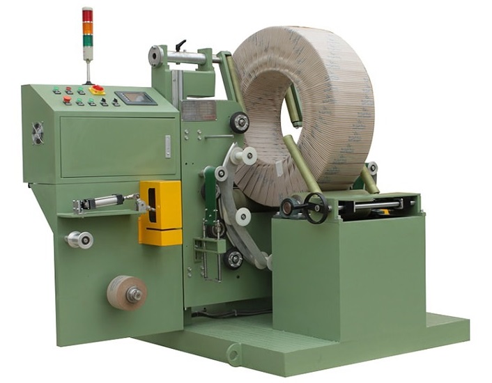
Tyre Packing Machine FPT-400
View Details →
Cable Coil Packing Machine-FPCA100
View Details →