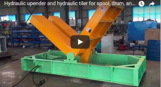
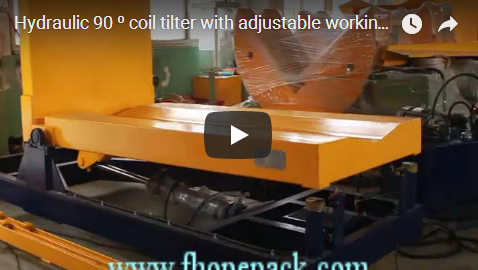
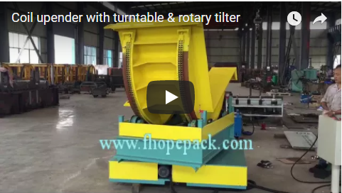
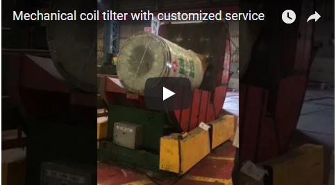
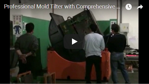
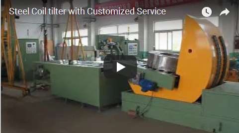
Executive summary This clip shows our coil tilter with a rotary base in our workshop. The orange V-cradle tilts through 90 degrees to turn a coil from eye-horizontal to eye-vertical or back, and the black base slews the whole tilter through 180 degrees. That way the coil is loaded from one side and leaves facing the next conveyor or the crane, without a second handling move.
Table of Contents
- What the clip shows
- Why add a rotary base
- Cycle per coil
- What we set per plant
- Selection checklist
- Safety
- Engineering FAQ
- Next step
- Related reading
- Sources
What the clip shows
| Step | What you see |
|---|---|
| Machine | An orange V-cradle tilter with an L-shaped table on a black rotary base |
| Tilting | The cradle tilts through 90 degrees, from V-cradle up to the flat table |
| Slewing | The base turns the whole tilter round through 180 degrees |
| Return | The cradle tilts back and the base returns to the load side |
| Workshop | Other FHOPE coil machines stand in the background |
Why add a rotary base
- One less move. The coil is tilted and turned in one station, so no crane move is needed to face it the right way.
- Flexible layout. Load and discharge can be on opposite sides of the tilter.
- Fits existing lines. The base points the coil at an existing conveyor or stacker.
- Safer handling. Operators stay outside the cell while the coil turns.
Cycle per coil
Worked example (illustrative).
| Item | Value |
|---|---|
| Tilt 90 degrees (illustrative) | 40 s |
| Slew 180 degrees (illustrative) | 30 s |
| Load, unload and return moves (illustrative) | 50 s |
| Cycle, 40 + 30 + 50 | 120 s |
| Coils per hour, 3,600 ÷ 120 | 30 coils |
What we set per plant
| Setting | Depends on |
|---|---|
| Cradle size | Coil OD, ID and width |
| Capacity | Heaviest coil |
| Slew angle | 180 degrees, or set per layout |
| Drive | Hydraulic or electric, per plant |
Selection checklist
- Coil weight, OD, ID and width.
- Tilt direction: eye-horizontal to eye-vertical or back.
- Slew angle needed.
- Load and discharge sides.
- Coils per hour.
- Pit or floor mounting.
Safety
- Fence the cell; keep clear of the slewing base and the cradle.
- Lock out before entering the cell.
- Use PU or rubber pads where the coil surface must not be marked.
- For CE markets, the machine is designed to ISO 12100 and EN 415-10.
Engineering FAQ
Q: What does the rotary base add? A: It slews the tilter through 180 degrees, so the coil leaves facing the next station.
Q: How far does the cradle tilt? A: Through 90 degrees, turning the coil from eye-horizontal to eye-vertical or back.
Q: How many coils per hour? A: About 30 coils per hour with an illustrative 120 s cycle that includes the return moves; real output depends on coil handling and layout.
Q: Can the slew angle be other than 180 degrees? A: Yes, we set it to suit the layout.
Q: Is the drive hydraulic? A: We supply hydraulic or electric drive, per plant.
Q: Which standards apply? A: For CE markets, ISO 12100 and EN 415-10.
Next step
We match a coil tilter with rotary base in three steps:
- Submit your layout drawing with coil weights and sizes, tilt direction and layout, to info@fhopepack.com.
- Receive a proposal within 48 hours with the machine data and layout.
- Book a site survey so we confirm the floor and crane layout.
Related reading
- 90-Degree Coil Upender with Rotary Base
- Hydraulic Coil Tilter for 90° Turning
- Coil Upender with Transfer Trolley
- Coil upender and tilter range
Sources
- Machine content: FHOPE engineering team, 2026-10-10
- Clip: the video on YouTube
- Cycle per coil: our worked example, illustrative values
- Standards scope: ISO 12100:2010; EN 415-10:2014
- Proposal timing: approved house CTA (proposal within 48 hours)
Last reviewed: 2026-10-10