Executive summary
Steel coils, large molds, dies, paper rolls and spools are heavy and awkward to turn, and manual handling is often impractical or unsafe. Hydraulic tilters and upenders rotate and reposition these loads in a controlled way, adding precision and safety to heavy material handling. We build hydraulic tilters and upenders. Load range and rotation needs are confirmed per project.
Table of Contents
- Why heavy loads are hard to turn
- What the machines do
- Tilters and upenders
- Controlled rotation
- The load range
- Precision and safety
- Typical configuration
- What the video shows
- Selection checklist
- Operation and safety
- Engineering FAQ
- Next step
- Related reading
- Sources and standards
Why heavy loads are hard to turn
Heavy, bulky and awkwardly shaped materials resist manual handling, and turning them by force risks both the crew and the product. Manual handling of these loads is often impractical and unsafe, and mechanical methods can become a bottleneck or damage the product. A controlled machine rotation changes all three. The load range and rotation needs are confirmed per project.
What the machines do
Hydraulic tilters and upenders lift and rotate heavy loads under control, taking loads from one orientation to another without straining the crew. The hydraulic action tilts and turns the load smoothly, keeping it stable through the motion. Machine rotation replaces the force and risk of turning by hand. The covered motions and load handling are confirmed per project.
Tilters and upenders
A tilter rotates the load to an angled position for access or presentation, while an upender takes the load through the vertical change it needs for the next step. Together they cover the rotations that heavy material handling asks for. The choice between tilter and upender follows the operation, confirmed per project. The right machine is the one that makes the needed move.
Controlled rotation
The machine rotates the load on controlled hydraulics, moving it smoothly and holding it at the set position. Controlled rotation is what protects both the load and the people near it, since nothing swings or drops. The load is turned at a pace and path the machine sets, not the force of a crew. The rotation speed and holding positions follow the load and step, confirmed per project.
The load range
The machines handle a heavy range: steel coils, large molds, dies, paper rolls and spools, the awkward loads of industrial floors. These share weight and awkward proportions, which is exactly what hydraulic rotation addresses. The load range and its weights are confirmed per project against the machines’ capacity. One machine covers the heavy mix a facility handles.
Precision and safety
Precision means the load arrives where the next step needs it, on the right face at the right angle, without damage. Safety means the crew is out of the path of the moving weight. The machine delivers both because the rotation is controlled and repeatable. Precision and safety together are why the machine replaces manual turning. The precision requirement is confirmed per project against the workflow.
Typical configuration
Figures below list functional design boundaries rather than numeric values, and are confirmed per project.
| Parameter | Typical range, confirmed per project |
|---|---|
| Load | coils, molds, dies, rolls, spools |
| Motion | tilt, upend |
| Drive | hydraulic |
| Position | set holding |
| Output | next-step ready |
| Electrical supply | 380 V three phase 50 Hz, or 220 V single phase for light machines, selected per project |
What the video shows
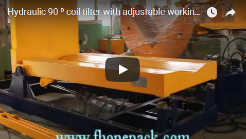
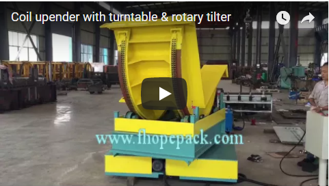
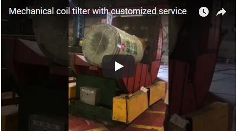
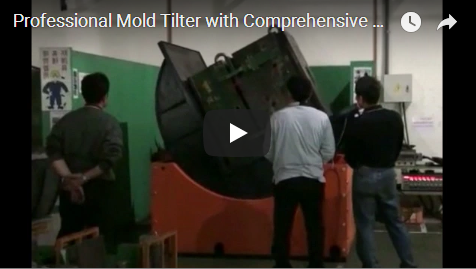
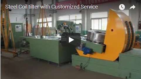
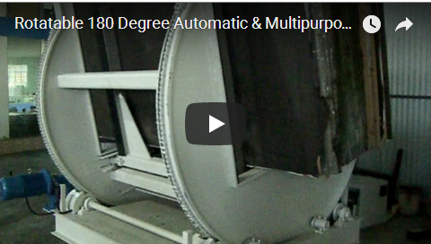
Our footage shows hydraulic tilters and upenders rotating heavy loads. It is a general demonstration, so your load range and rotation needs are confirmed with us per project.
Selection checklist
| Question | Confirm per project |
|---|---|
| Load range | sizes, weights |
| Motion | tilt, upend |
| Rotation | travel, path |
| Position | holding |
| Output | next-step fit |
| Electrical supply | voltage, phase and frequency on site |
Operation and safety
Run the load from the panel and the machine tilts or upends it under hydraulics automatically. Keep clear of the load path and moving table while the machine runs, with guarding and emergency stops at the operator position. Routine checks cover the hydraulics, table, holding mechanisms, sensors and control, per the machine manual. Confirm the rotation sequence against the load before each run so loads move without damage.
Engineering FAQ
Q: Why automate load rotation? A: Manual turning of heavy awkward loads is impractical, unsafe and slow.
Q: What is a tilter? A: It rotates a load to an angled position for access or the next step.
Q: What is an upender? A: It takes the load through the vertical change the workflow needs.
Q: How does it move a load? A: On controlled hydraulics, smoothly and holding at each set position.
Q: What loads does it handle? A: Steel coils, molds, dies, paper rolls and spools, confirmed per project.
Next step
- Email us at info@fhopepack.com with your load range, rotations and layout.
- We send a tilter and upender proposal and a layout drawing within 48 hours.
- We arrange a site survey to confirm load range and workflow rotation.
Related reading
- 180° Upender: Operation and Applications
- Hydraulic tilter and upender for heavy loads
- Steel coil packing machine for coils upender
- FHOPE packing machinery product lines
Sources and standards
- ISO 12100:2010 Safety of machinery, general principles for design and risk assessment
- EN 415-10:2014 Safety of packaging machines, general requirements
- EN ISO 13849-1:2023 Safety of machinery, safety-related parts of control systems
FHOPE hydraulic tilter and hydraulic upender demonstration video. Reviewed as a general demonstration; load range confirmed per project.
Last reviewed: 2026-10-10