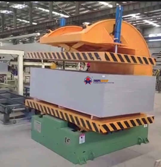
Executive summary The clip shows a floor-mounted hydraulic tilter take a strapped test load from horizontal to near-vertical and back in one continuous cycle of about 16 s. The footage is not from our shop floor, so below we treat it as a reference cycle and map it to our equivalent hydraulic coil upender range (FPCT). You get the motion the clip shows, the FPCT load and speed table, and the checks we run before a tilter is built into a coil line.
Table of Contents
- What the clip shows
- Why a dedicated hydraulic tilter beats crane flipping
- Our FPCT hydraulic coil upender range
- Matching load, table and cycle to the project
- Selection checklist for a coil tilter
- Controls and safety
- Engineering FAQ
- Next step
- Related reading
- Sources
What the clip shows
| Clip time | What is on screen |
|---|---|
| 0–4 s | Platform horizontal; four white rectangular packages strapped together sit on the orange deck |
| about 8–12 s | Platform near vertical after a hydraulic lift through about 90° |
| about 12–16 s | Platform returns to horizontal; full up-and-back cycle about 16 s |
Times come from frames taken every 4 s. The base is a green floor frame on leveling feet, with a hydraulic cylinder on the side and a control cabinet with an emergency stop and a start button. A yellow guard sits on the top edge of the platform. No people appear in the clip.
The load in the clip is a strapped package stack used to show the motion. On a production coil upender the same L-frame or cradle carries a steel, aluminum or copper coil, or a palletised coil, sized to the table.
Why a dedicated hydraulic tilter beats crane flipping
Crane flipping a coil with slings puts the load under a swinging hook and asks the rigger to control the Centre of Gravity by hand. A floor-mounted hydraulic tilter keeps the load on a fixed pivot and drives the turn with a cylinder, so the path is repeatable from cycle to cycle.
Three points decide when a tilter is the right station:
- Orientation change is daily work, not a rare move — for example eye-to-sky packing after eye-to-wall storage, or the reverse before a decoiler.
- The load has a clear CoG that sits inside the cradle or table once the coil is centred.
- The next station wants a fixed hand-off height, which a tilter can hold at the end of the stroke.
Our hydraulic coil upenders are built for that role: tilt between horizontal and vertical, with the table sized to the coil and the speed set in the hydraulic circuit.
Our FPCT hydraulic coil upender range
Published FPCT models from our coil upender range:
| Model | Max load | Power | Cycle time (approx.) | Machine weight |
|---|---|---|---|---|
| FPCT-02 | 2 t | 1.5 kW | 50–70 s | 2.0 t |
| FPCT-05 | 5 t | 1.5 kW | 50–80 s | 2.5 t |
| FPCT-10 | 10 t | 3.2 kW | 60–90 s | 3.0 t |
| FPCT-20 | 20 t | 4.5 kW | 60–90 s | 3.5 t |
| FPCT-30 | 30 t | 6.5 kW | 60–90 s | 4.0 t |
| FPCT-50 | 50 t | 11.5 kW | 60–100 s | 4.5 t |
Table size and overall machine size are designed per coil size. Power supply is set to the site voltage and frequency. Warranty on the range is 2 years.
The clip cycle of about 16 s is faster than the published FPCT band. That is expected: the clip load is a light strapped package stack, while the FPCT times are stated for the rated coil load of each model. When we size a tilter we set cylinder speed against the real coil weight, not against a light demo load.
Matching load, table and cycle to the project
| Project input | What we fix on the machine |
|---|---|
| Max coil weight | FPCT model (2–50 t) |
| Coil OD, ID, width | Table / cradle size |
| Start and end orientation | Horizontal ↔ vertical stroke and end stops |
| Hand-off height to the next conveyor or car | Platform height at each end of stroke |
| Target cycle time at rated load | Hydraulic flow and valve setting |
A hydraulic drive is the usual choice when the coil is heavy and the turn must stay smooth.
Selection checklist for a coil tilter
- Max coil weight and the heaviest coil that will sit on the table every shift.
- Coil OD, ID and width, including the tallest eye-to-sky package.
- Start orientation and end orientation (eye to sky / eye to wall).
- Whether the load arrives as a bare coil, a palletised coil or a strapped package.
- Hand-off height to the next conveyor, coil car or packing station.
- Guarding, light curtains and access routes around the pivot.
- Destination market (CE or other) for the risk assessment package.
Controls and safety
The standards that apply depend on the destination market. For CE markets, ISO 12100 sets the risk-assessment method and EN 415-10 covers general requirements for packaging machines, which fixes guarding and the emergency-stop arrangement. Tilters, upenders and inverters fall under that pair.
On a hydraulic tilter we check, at least:
- Emergency stop on the cabinet and any remote station.
- End-of-stroke limits so the platform cannot overrun.
- Guarding or a marked exclusion zone around the swing of the load.
- Overload protection in the hydraulic circuit sized to the FPCT model.
The yellow guard on the platform edge in the clip is one local measure; the full guarding package is fixed in the risk assessment for each layout.
Engineering FAQ
Q: Is the machine in the clip one of our FPCT upenders? A: No. The clip is a reference cycle only; we supply our equivalent FPCT hydraulic coil upender, sized to your coil weight and table size.
Q: Why is the clip cycle about 16 s while FPCT times are 50–100 s? A: The clip turns a light strapped package stack. FPCT cycle times (50–100 s) are stated for the rated coil load of each model; we set cylinder speed to the real coil weight.
Q: What loads can an FPCT upender turn? A: The published range covers 2 t to 50 t (FPCT-02 to FPCT-50). Table size is designed per coil size.
Q: Can the same tilter handle steel and aluminum coils? A: Yes, when the cradle or table is built for the coil OD/ID/width and the surface contact is agreed (bare steel vs soft pads for finished aluminum).
Q: Which standards apply to a coil tilter? A: For CE markets, ISO 12100 for risk assessment and EN 415-10 for packaging-machine requirements, including guarding and emergency stop.
Q: What drive power does the FPCT series use? A: Motor power is 1.5 kW on FPCT-02 and FPCT-05, then 3.2 / 4.5 / 6.5 / 11.5 kW up to FPCT-50.
Q: Can the tilter hand off to a conveyor or coil car? A: Yes. Platform height at both ends of the stroke is set to match the receiving conveyor, coil car or packing station.
Next step
We plan a coil tilter or upender station in three steps:
- Submit your layout drawing with coil weight, OD/ID/width and start/end orientation, to info@fhopepack.com.
- Receive a proposal within 48 hours, with the FPCT model, table size and hand-off height.
- Book a site survey so we confirm floor loading, guarding and the link to the next conveyor or coil car.
Related reading
- Upender with Custom Fixture for Heavy Castings: 90° L-Frame Turn of a Cast Housing
- Steel Sheet Upender for 180 Degree Safety Turning: Chain Turner or C-Type Inverter
- Coil Tilter and Upender: 90° Turn of a Palletised Coil
- Coil Tilter with Sliding Table: 90° Turn and Return
- Coil upender
Sources
- Machine in action (reference clip, non-own footage): the video on YouTube
- FPCT-02…FPCT-50 load, power, cycle time, machine weight, table per coil size, 2-year warranty; tilt between horizontal and vertical: Coil upender / Hydraulic coil upender
- Standards scope: ISO 12100:2010; EN 415-10:2014
- Proposal timing: approved house CTA (proposal within 48 hours)
Last reviewed: 2026-10-07