Executive summary A steel coil has no flat face to stand on and every physical reason to roll. An industrial coil tilter (coil upender/downender) safely reorients master and slit coils through 90 degrees between vertical (eye-to-sky) storage and horizontal (eye-to-wall) decoiling. By capturing the load within a rigid, powered L-shaped cradle, the system eliminates hazardous crane-and-sling tipping operations, mitigates outer-wrap edge deformation, and secures structural stability across the entire center-of-gravity transition.
Table of Contents
- The turning problem
- What a coil tilter does
- Cradle designs
- Where it fits the line
- Core components
- Typical configuration
- Cycle and control
- Selection checklist
- Controls and safety
- Engineering FAQ
- Next step
- Related reading
- Sources and standards
The turning problem
Heavy gauge steel coils present fundamentally opposing handling demands between storage and processing:
- Storage orientation (Eye-to-sky / Vertical axis): Slit mults and banded coils are typically stacked bore-vertical to maximize plant floor utilization, stabilize loose wraps, and prevent uncontrolled rolling.
- Processing orientation (Eye-to-wall / Horizontal axis): Uncoilers, slitting lines, stamping mandrels, and cut-to-length feeds require coils bore-horizontal to accept expanding cantilevered mandrels.
Eye-to-Sky (Vertical Axis)                Eye-to-Wall (Horizontal Axis)
      ┌───────────┐                             ┌───────────┐
      │   ┌───┐   │  ── 90° Powered Cradle ──>  │ (O) Bore  │
      │   └───┘   │     (Zero Sling Drag)       │           │
      └───────────┘                             └───────────┘
   Stable Warehousing                      Decoiler / Mandrel Feed
Handling this 90° transition using conventional overhead bridge cranes, standard wire rope slings, or C-hooks introduces severe kinetic hazards. As the coil tips past its balance center, dynamic momentum causes uncontrolled load swing, side-loading risks on crane hoists, sling slippage across sharp outer edges, and irreversible edge crimping on prime steel stock.
A dedicated mechanical or hydraulic coil tilter anchors the coil throughout the full 90-degree quadrant, distributing bearing pressure across structural bed faces and eliminating unconstrained gravitational shifts.
What a coil tilter does
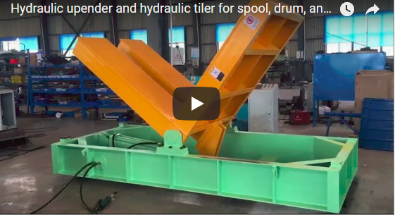
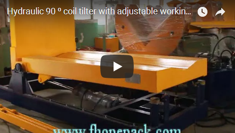
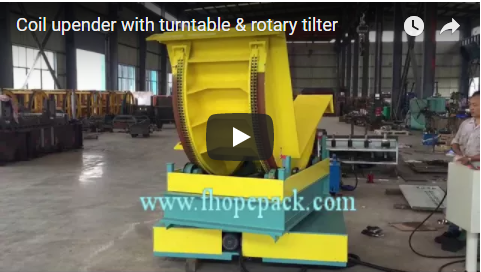
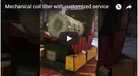
A steel coil tilter—also designated as a coil upender (turning eye-vertical to eye-horizontal) or downender (turning eye-horizontal to eye-vertical)—executes a continuous, powered 90-degree reorientation cycle.
Unlike hoisting tackle that applies localized tensile forces to coil edges, the tilter secures the payload within a rigid, dual-surface orthogonal cradle. The machine functions bidirectionally:
- Upending sequence: Receives strapped slit coils from palletizing stations or transfer cars with the eye vertical, rotates the cradle 90°, and presents the coil with its bore horizontal for C-hook or coil car extraction.
- Downending sequence: Receives prime master coils directly from bay delivery vehicles or uncoilers, lowering them 90° onto flat pallets for banding, packing, or vertical racking.
Cradle designs
Cradle geometry dictates load stabilization and surface protection during the rotation arc.
| Cradle Platform Type | Surface Configuration | Primary Industrial Use |
|---|---|---|
| V-Saddle Cradle | 90° to 120° V-profile, lined with 85–95 Shore A replaceable polyurethane or UHMW-PE pads | Holds bare round master coils; centers the outer diameter without edge crimping or surface marring. |
| Flat Deck Platform | Heavy structural steel flat plate, optional integrated timber or polymer runners | Accepts coils pre-loaded on wooden skids, steel transfer pallets, or flat containers. |
| V-Saddle + Flat Hybrid | One face configured as a central V-groove, adjacent 90° face configured as a solid flat plate | Standard dual-purpose design: receives eye-to-sky coils on pallets, rotates to eye-to-wall resting in V-grooves. |
| Slotted / Fork Cradle | Deep clearance slots machined into the cradle decks | Enables direct in-and-out access for C-hooks, forklift prongs, or coil transfer car lifters. |
Where it fits the line
Coil tilters function as the critical transfer interface across multiple metals processing stages:
- Steel service centers: Upending packaged slit coils from slitting line run-out turnstiles to downstream automated strapping lines.
- Stamping and roll-forming plants: Downending incoming deliveries onto decoiler transfer tracks feeding high-tonnage automotive press beds.
- Master coil packing lines: Orienting coils prior to circumferential stretch wrapping, radial paper packaging, and steel eye-strapping.
- Warehouse sorting bays: Repositioning inventory between ground-level V-storage bunks and high-density vertical pallet racks.
[Slitting / Decoiling Line]
            │
      (Eye-to-Wall)
            ▼
┌───────────────────────────────┐
│  Industrial 90° Coil Tilter   │ ◄── Interlocked Zone / Conveyor Feed
└───────────────────────────────┘
            ▼
      (Eye-to-Sky)
            │
[Strapping / Pallet Packaging]
Core components
| Subsystem | Engineering Specification | Functional Role |
|---|---|---|
| Base Chassis | Heavy-duty welded ASTM A36 / Q235B structural beam weldment | Anchors the unit to plant foundations; dissipates dynamic overturning moments during tilt. |
| Tilting Cradle | Reinforced orthogonal L-frame with machined rocker arcs or heavy pivot trunnions | Sustains combined radial and axial coil weight vectors throughout the 0°–90° arc. |
| Drive Mechanism | Mechanical: Dual heavy-pitch roller chains with SEW/Nord helical-worm geared brake motors. Hydraulic: Double-acting cylinders with hardened chrome rods and pilot-operated check valves. |
Delivers positive rotational torque and ensures absolute mechanical locking during mid-cycle power failure. |
| Bearing System | Heavy spherical roller pillow block bearings or hardened machined guide rollers | Supports radial reaction loads at the rocker radius, ensuring smooth angular acceleration. |
| Control Console | IP54/IP65 pendant station, remote push-button console, or integrated Siemens/Allen-Bradley PLC cabinet | Governs forward/reverse rotation, variable frequency speed ramps, and machine interlocks. |
Typical configuration
The following parameters represent standard engineering configurations across light, medium, and heavy-duty industrial classes:
| Engineering Parameter | Light to Medium Duty | Heavy Mill Duty |
|---|---|---|
| Rated Load Capacity | 2,000 kg – 10,000 kg (2 t – 10 t) | 15,000 kg – 50,000 kg+ (15 t – 50 t+) |
| Tilt Angle | 90° standard (adjustable limits ±2°) | 90° standard (special multi-angle up to 180°) |
| Full Cycle Duration | 25 – 45 seconds (90° traverse) | 45 – 90 seconds (controlled acceleration) |
| Max Coil Outer Diameter (OD) | 800 mm – 1,500 mm | 1,200 mm – 2,300 mm |
| Coil Width / Stack Height | 300 mm – 1,200 mm | 500 mm – 2,200 mm |
| Drive System | Mechanical gearmotor with dual drive chains | Dual heavy-duty hydraulic cylinders with power pack |
| Installed Motor Power | 3.0 kW – 7.5 kW | 11.0 kW – 30.0 kW (Hydraulic unit) |
| Electrical Supply | 380 V – 480 V, 3-Phase, 50/60 Hz | 380 V – 480 V, 3-Phase, 50/60 Hz |
Cycle and control
A standard machine duty cycle operates under strict continuous-engagement protocols:
- Load entry: The coil is seated against the lower cradle bed using a plant forklift, C-hook, or upstream motorized roller conveyor. In V-saddle units, the coil automatically centers itself along the cradle’s longitudinal midline.
- Tilt cycle engagement: The operator initiates rotation via dual-hand controls or a maintained hold-to-run push button.
- Over-center transition: As the cradle reaches the 40°–50° quadrant, the load vector shifts across the pivot axis. The variable-frequency drive (VFD) applies controlled dynamic braking, or counter-balance hydraulic valves throttle fluid return, preventing gravitational free-fall.
- Target rest and discharge: Proximity limit switches decelerate the cradle to a creep speed before reaching mechanical hard stops at exactly 90°. The coil is extracted in its new orientation via downstream coil car, walkie-stacker, or driven roller deck.
Selection checklist
Evaluate the following operational criteria prior to final machine specification:
| Evaluation Item | Critical Engineering Input | Impact on Machine Build |
|---|---|---|
| Maximum & Minimum Payload | Heaviest coil mass (t) and lightest operating unit | Defines structural steel gauge, pivot shaft diameter, and hydraulic relief settings. |
| Dimensional Envelope | Minimum ID, maximum OD, and maximum coil width (face) | Establishes cradle L-dimension, V-angle spread, and fork clearance cutouts. |
| Packaging & Outer Surface | Bare steel, dry, oiled, paper-wrapped, or palletized | Determines cradle lining (bare steel vs. high-density polyurethane). |
| Drive Architecture | Production throughput (cycles/hour) and duty rating | Electro-mechanical chain drive for high-speed continuous cycles; hydraulic for extreme tonnages. |
| Line Layout & Material Flow | Infeed/discharge heights and transport method | Dictates foundation mounting (surface pit mounted vs. floor-level flush installation). |
Controls and safety
Industrial coil upenders handle immense mass within a compact footprint. Safety designs must satisfy international machinery standards including ISO 12100 and EN 415-10:
- Fail-safe holding: Mechanical models incorporate spring-set electromagnetic disc brakes that lock instantly upon power interruption. Hydraulic units employ dual pilot-operated check valves flanged directly onto the cylinder ports to prevent rod drift or collapse under line pressure loss.
- Hold-to-run logic: Standard operator stations employ “dead-man” controls, requiring intentional, sustained input throughout the rotational cycle.
- Zone isolation: Integration with safety light curtains, perimeter safety fencing, and pressure-sensitive floor mats prevents machine actuation whenever personnel cross the rotational perimeter.
- Over-travel protection: Redundant electromechanical limit switches and solid polyurethane mechanical buffer stops prevent cradle over-travel past the 90° limit.
Engineering FAQ
Q: Can a single tilter handle both palletized and bare steel coils? A: Yes. A hybrid cradle configured with a flat decking plate on one leg and a polyurethane-lined V-saddle on the adjacent 90° leg accommodates bare round coils in the horizontal position and flat wooden skids in the vertical position.
Q: What prevents the cradle from dropping if power fails mid-tilt? A: Mechanical tilters use self-locking worm reducers paired with fail-safe spring-applied motor brakes. Hydraulic tilters incorporate hard-plumbed pilot-operated check valves and counter-balance valves directly into the cylinder manifolds, locking the fluid column rigidly in place.
Q: Is pit mounting preferred over floor surface mounting? A: Pit mounting brings the lower cradle deck flush with the factory finished floor, allowing direct roll-on or pallet-jack loading. Surface-mounted units require no civil pit excavation but must be fed by forklifts, overhead cranes, or dedicated inclined ramps.
Q: What cycle time can be expected for a 90-degree turn? A: Rotational cycle duration ranges from 30 seconds for small 3-tonne coils up to 75 seconds for heavy 30-tonne master coils. Acceleration and deceleration curves are shaped via VFD or proportional hydraulic valves to safeguard coil wrap integrity.
Next step
- Provide your maximum and minimum coil parameters (OD, ID, width, and gross weight) along with plant floor layout constraints to info@fhopepack.com.
- Our packaging engineering team delivers general arrangement (GA) drawings, load calculation summaries, and drive recommendations within 48 hours.
- Schedule an on-site or virtual engineering review to verify bay crane clear-heights and infeed conveyor alignments.
Related reading
- Coil tilter and coil upender
- Automatic & multipurpose tilter for box
- Professional mold tilter with comprehensive technical support
- FHOPE packing machinery product lines
Sources and standards
- ISO 12100:2010 — Safety of machinery. General principles for design, risk assessment and risk reduction
- EN 415-10:2014 — Safety of packaging machines. General requirements
- EN ISO 13849-1:2023 — Safety of machinery. Safety-related parts of control systems
- FHOPE industrial steel coil tilter field commissioning data and engineering design standards.
Last reviewed: 2026-10-10
Author: Principal Packaging Machinery Engineering Team