Overview
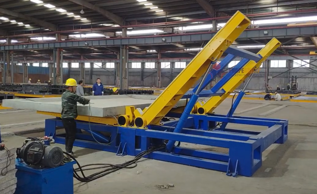
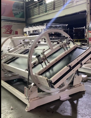
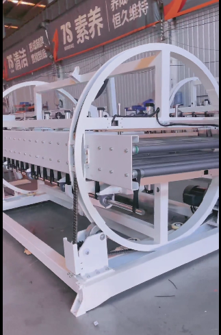
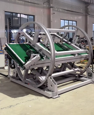
For plant engineers and procurement teams sourcing a custom 180° sheet and plate turnover machine, factory testing before shipment is the primary safeguard against costly commissioning failures. A 180° turnover machine handles heavy, awkward slabs—such as steel plates, precast panels, or heavy dies—and transfers them across two tilting tables. Testing the machine inside the manufacturer's factory verifies mechanical synchronization, hydraulic pressure retention, safety interlocks, and sensor positions before equipment is crated and shipped.
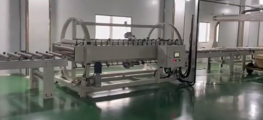
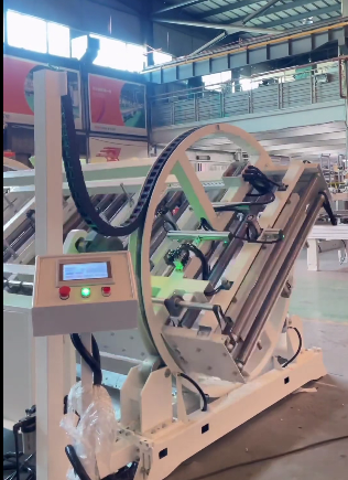
The video below illustrates custom 180° sheet and plate turnover machines undergoing operational testing inside the maker's facility:
What Factory Testing of a Turnover Machine Covers
Factory acceptance testing (FAT) for a two-table hydraulic turnover machine covers both extended endurance and electro-hydraulic safety logic. According to the manufacturer's operational practices, turnover units undergo verification before dispatch:
- Extended run verification: The maker's stated testing protocol includes near-continuous cycling (up to about 24 hours of non-stop run time) to surface thermal build-up, seal leakage, or sensor drift over repeated cycles. This is the manufacturer's declared endurance routine for this machine family; it is not a per-machine legal measurement, so it belongs on your acceptance evidence list to confirm per unit.
- Control and emergency systems: Testing confirms smooth acceleration and deceleration, responsive control, and immediate emergency-stop cutoff.
Beyond basic cycling, a comprehensive factory test validates the mechanical and hydraulic milestones that govern 180° sheet manipulation:
| Test Item | Verification Objective | Engineering Criteria |
|---|---|---|
| No-Load Cycling | Table travel, dual-table alignment, and return strokes. | Smooth movement without binding; mechanical stop blocks reach correct physical limits. |
| Photoelectric Handover | Sensor triggering during the table-to-table load transfer. | Photoelectric sensor triggers near 85° before the center of gravity crosses vertical, so the secondary table receives the part. |
| Stop & Hold at Angle | Ability to freeze motion and hold position under load. | Drive holds position at any intermediate angle; the hydraulic circuit maintains pressure. On the 180° reference build in this machine family this is rated up to 15 MPa working pressure, with 20 MPa as the maximum design allowance. |
| Power-Loss Locking | Safety response during an unexpected electrical outage. | Hydraulic pressure-hold locks prevent table collapse; the system resets softly when power returns. |
| Emergency Stop & Interlocks | Swept-area safety perimeter and cycle cutoff. | Instant cycle stop when the emergency stop is tripped; physical guarding and interlocks conform to ISO 12100 risk-assessment principles. |
| Structural Limits | Travel boundary protection. | Electric limit switches and mechanical hard stops halt travel safely at positive mechanical stops. |
These checks reference established industrial machinery benchmarks, including EN 415-10 harmonized standards and ISO 12100 risk-reduction procedures.
Why In-Factory Testing Mitigates On-Site Project Risk
Rectifying an alignment or hydraulic fault inside the maker's plant is straightforward: design engineers, machining tools, replacement hydraulic seals, and overhead cranes are readily accessible. Discovering the same issue after delivery on your factory floor causes immediate operational bottlenecks.
| Operational Factor | Discovered Inside Maker's Factory | Discovered On Your Floor |
|---|---|---|
| Crane & Rigging Access | Dedicated shop cranes available continuously | Requires renting mobile cranes or tying up plant production cranes |
| Hydraulic Adjustments | Immediate pressure re-tuning on the test rig | Field service dispatch, travel latency, and production-bay downtime |
| Sensor & Logic Retest | Immediate PLC reprogramming by controls team | Remote debugging or a scheduled field-service intervention |
| Financial Acceptance | Flaws resolved before capital release | Capital committed while equipment stands idle in staging |
Factory pre-testing turns on-site commissioning into a planned verification of previously proven parameters rather than an open-ended troubleshooting exercise.
Custom Dimensions and Parameters That Govern Machine Sizing
A 180° sheet turnover machine is not an off-the-shelf catalog frame. This machine family builds both mechanical upenders (product-line range roughly 1–60 tonnes) and heavy-duty hydraulic configurations (product-line range roughly 1–100 tonnes, for example the 12-tonne reference build in the FPFT class). Fabricating and testing a custom machine requires precise operational inputs from the buyer:
| Customer Input | Engineering Significance | Testing Implication |
|---|---|---|
| Part Geometry (L × W × Thickness) | Determines table platform dimensions and support layout. | Verified against the maximum plate footprint to confirm table clearance and edge support. |
| Maximum Load Weight | Dictates hydraulic cylinder bore, pump motor output, and structural steel sizing. | Determines the proof-test weight for loaded cycling up to rated capacity. |
| Material Characteristics | Steel plate, precast concrete, mould tooling, or stacked laminates. | Determines table contact surface (bare steel or buffered supports). |
| Turning Sequence | Full 180° inversion vs. intermediate stops (e.g. 90° for edge inspection). | Confirms the circuit holds a steady position at partial tilt angles without creeping. |
| Infeed/Outfeed Interface | Overhead crane, forklift tines, or automated conveyor. | Defines physical clearance around the swept perimeter and loading height. |
| Throughput Target | Cycles required per hour or shift. | Sets hydraulic pump flow rate and cycle speed within thermal operating limits. |
These inputs are confirmed on engineering approval drawings before fabrication, establishing the baseline against which factory testing is measured.
Factory Acceptance Checklist: What to Confirm Before Shipment
Before releasing final payment and authorizing dispatch, procurement and engineering teams should request formal documentation of the factory test:
- Continuous run documentation. A test log confirming the machine completed its factory burn-in (in line with the maker's stated up-to-about-24-hour protocol) without thermal alarms or fluid leaks, and stating whether the run was unloaded or under load.
- Hydraulic pressure and hold record. A test certificate showing the hydraulic unit maintained its working pressure and held position at intermediate angles without cylinder drift.
- Sensor and handover verification. Sign-off that the near-85° handover sensor and electric limit switches stopped table motion as designed.
- Power-failure simulation. Physical confirmation that simulating a sudden power loss locked the tilting tables securely without dropping the test load.
- Compliance documentation. Confirmation of the safety references used (EN 415-10 as reference and an ISO 12100 risk assessment).
- Site commissioning scope. A clear written definition of installation assistance, commissioning support, and availability of local on-site technicians.
Upon machine arrival, repeating this core checklist on your floor—empty travel, a rated-weight cycle, the emergency stop, and the power-loss lock—completes the acceptance loop cleanly.
Frequently Asked Questions
Q: Why does the manufacturer recommend an extended pre-delivery run test? A: Running a hydraulic turnover machine over an extended period (up to about 24 hours under the manufacturer's declared protocol) allows hydraulic oil to reach operating temperatures, revealing seal leaks, pressure-valve instability, or sensor vibration issues that do not appear during a brief demonstration.
Q: How does a two-table 180° machine safely transfer heavy plates mid-turn? A: Table A lifts the plate until it approaches about 85°. A photoelectric sensor detects table position and halts rotation just before the load's center of gravity passes vertical. Table B then swings up to meet the plate, receives the load securely, and both tables lower in controlled synchronization so the workpiece lands flat on its opposite face.
Q: What prevents a heavy steel plate from falling if power fails mid-cycle? A: The hydraulic circuits hold pressure and mechanical lock blocks secure the tables. If electric power drops, the tables lock in position. When power is restored, the control system initiates a soft, controlled reset rather than a sudden drop.
Q: What is the capacity range for mechanical versus hydraulic turnover machines? A: Mechanical upenders in this product line generally cover about 1–60 tonnes, while hydraulic configurations cover about 1–100 tonnes, allowing heavy slab, mould, and coil turnover under controlled operation.
Q: Does factory testing eliminate the need for on-site commissioning? A: No, but it shortens it substantially. Factory testing confirms the machine functions correctly as a standalone unit. On-site commissioning then focuses on floor anchoring, local utility hookup, and integrating the unit with your specific cranes or feeding systems.
Next Steps
To configure a turnover machine matched to your facility, compile your maximum plate dimensions (length, width, thickness), heaviest part weight, infeed handling method (crane or forklift), and target cycle rate. Providing these specifications allows the engineering team to generate layout drawings, define the custom hydraulic power unit requirements, and formulate an agreed factory acceptance testing plan.
Related Resources
- Coil Upender & Industrial Turnover Solutions – Technical overview of custom mechanical (≈1–60T) and hydraulic (≈1–100T) turnover equipment.
- How 180° Turning Machines Work for Precast Components and Sheets – Detailed breakdown of two-table hydraulic kinematics, the near-85° handover sensor, and EN 415-10 / ISO 12100 safety references.