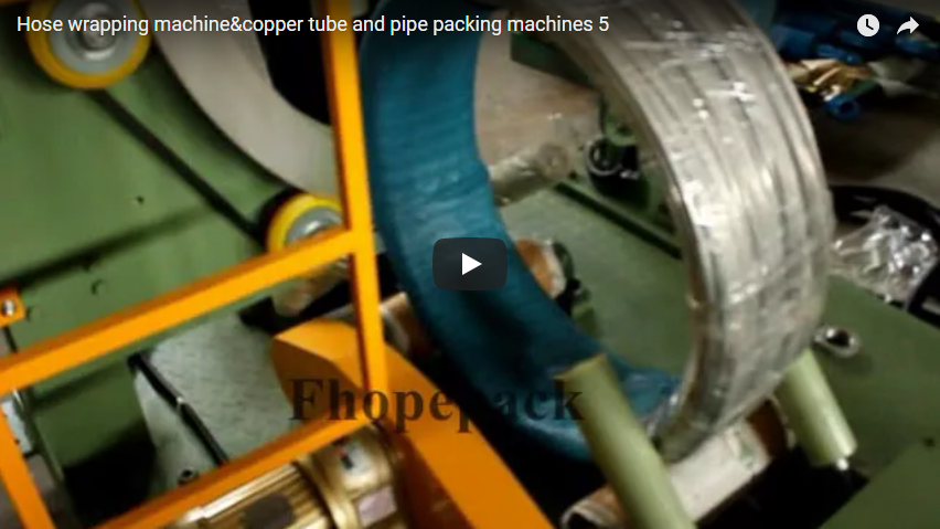
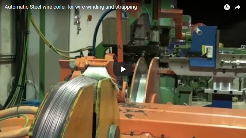
Executive Summary: Engineered for precision bearing rings, slewing bearings, and machined hubs, this semi-automatic horizontal orbital wrapping system integrates an automated wrapping ring with a pneumatic/hydraulic elevator station. By halting the operational cycle at a defined “lifter-up” position, the machine provides an ergonomic, zero-strain loading height for operators while ensuring repeatable film tension and multi-layer corrosion protection (VCI + PE stretch film) across varied product runs.
The Machine: System Architecture & Operation
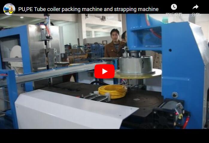
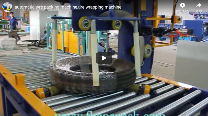
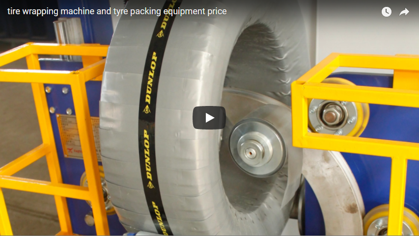
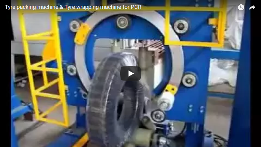
This specialized packaging system applies protective stretch film to ring-shaped components—such as radial bearings, heavy slewing rings, and machined wheel hubs. Built specifically for medium-volume manufacturing plants and mixed-model assembly lines, the equipment bridges the gap between labor-intensive manual packaging and complex, oversized fully automatic conveyor lines.
[Unloading / Loading Station] ── (Ergonomic Lifter) ──► [Centering & Orbital Wrapping Zone]
        ▲                                                               │
        └────────────────── (Finished Component Return) ────────────────┘
The system integrates three core sub-assemblies controlled via a centralized Siemens/Mitsubishi PLC:
- Orbital Wrapping Ring: A high-rigidity rotating ring driven by dual-friction PU wheels that guides the film carriage smoothly through the inner bore and around the outer perimeter of the component.
- Integrated Lifter (Elevator) Station: A vertical positioning platform driven by guided cylinders with pilot-operated check valves, raising the workpiece to a calibrated transfer height (typically 750–850 mm above floor level) for safe material handling.
- Film Dispensing Carriage: Equipped with an adjustable mechanical friction brake or powered pre-stretch rollers (up to 200%), allowing precise film elongation without distorting lightweight retainers or internal bearing raceways.
Because loading and unloading occur at a single station, the system occupies a minimal floor space footprint and eliminates extensive infeed and outfeed roller conveyors.
Confirmed Operating Cycle: 10-Step Sequence
The control logic follows a strict “hold-at-top” sequence to protect both the operator and the precision-ground surfaces of the bearing. The cycle never indexes into the next packaging phase without an explicit operator release command.
| Step | Machine Action & Kinematics | Operator & Safety Interface |
|---|---|---|
| 01 | The previously wrapped component returns from the wrapping zone to the elevator station. | Operator visual check; station clear. |
| 02 | The elevator lifts the component to the designated ergonomic unloading height (750–850 mm). | Mechanically guided vertical ascent; pilot check valves lock position. |
| 03 | Machine halts the cycle at “Lifter Up”; drive motors de-energize to standby. | Dual optical safety sensors verify upper travel limit. |
| 04 | Operator clears the wrapped component using a shop crane, manipulator, or manual pick. | Lifter remains locked at working height. |
| 05 | Operator positions an unpackaged bearing onto the protective support fixtures of the lifter. | Gravity centering / V-block alignment guide. |
| 06 | Operator presses the Cycle Start dual-pushbutton / foot switch outside the hazard zone. | PLC confirms safety light curtains and interlocks are clear. |
| 07 | The lifter descends to the wrapping center line; drive rollers engage the inner bore. | Controlled pneumatic/hydraulic descent with flow restrictor cushioning. |
| 08 | Wrapping Sequence: The ring rotates around the bearing while support rollers index the component. | Film applied with programmed overlap (30%–70%) and controlled tension (15–40 N). |
| 09 | Film tail is clamped and severed; the wrapped component shifts back to the elevator base. | Drive rollers disengage smoothly. |
| 10 | The elevator raises the component; the system halts at “Lifter Up” to complete the loop. | Cycle completes; system waits for Step 04. |
By halting automatically at the raised position, the machine guarantees a standardized physical handover. Operators never reach into moving assemblies, and heavy components are consistently loaded and unloaded at an optimal ergonomic posture.
Technical Specifications & Engineering Considerations
Before finalizing machine design and structural fabrication, our engineering team requires confirmation of the following operating boundaries:
1. Workpiece Envelope & Dynamic Load Capacities
- Diameter Limits: Confirm minimum internal diameter (ID) to ensure carriage pass-through clearance, alongside maximum outer diameter (OD).
- Width & Weight Limits: Verify minimum and maximum bearing ring heights (W) and overall mass (kg). For workpieces exceeding 35 kg, overhead hoist or vacuum lifting aids should be incorporated at the lifter perimeter.
2. Wrapping Materials & Atmospheric Sealing
- Film Compatibility: Standard polyethylene (LLDPE) machine stretch film (17–35 µm), Volatile Corrosion Inhibitor (VCI) film, or coated crepe kraft paper.
- Overlap & Layer Programming: Overlap rates are set on the HMI from 30% to 70%: Overlap % = (1 − V_traverse ÷ (N_ring × W_film)) × 100
- Set overlap ratios to 50% or higher when packing anti-rust-treated bearings to ensure a watertight and airtight seal.
3. Functional Safety & Industrial Standards
- Design Standards: Risk assessment conducted under EN ISO 12100; packaging machinery protective requirements comply with EN 415-10.
- Safety Architecture: Perimeter physical fencing, Cat. 4 / PL e optical safety light curtains at the loading portal, and an integrated emergency stop circuit (E-stop) wired directly to safe-off contactors.
- Lockout/Tagout (LOTO): Standard isolator switches installed for pneumatic dump valves and main electrical supply.
4. Electrical & Plant Utilities
- Controls & Interface: Multilingual industrial HMI touchscreen (English, German, or regional options). Remote diagnostics via industrial Ethernet available.
- Utility Specifications: Supply voltage 380V/415V/480V (3-phase, 50/60 Hz); clean, dry compressed air supply at 0.5–0.7 MPa.
Why Precision Bearings Demand Automated Machine Wrapping
High-precision bearings, slewing rings, and matched bearing assemblies feature ultra-fine ground raceways that are highly vulnerable to humidity, airborne particulates, and storage oxidation. Manual wrapping poses three key engineering challenges:
- Inconsistent Film Tension: Manual hand wrapping yields variable clamp force across the ring profile. Loose wraps permit air and moisture ingress; excessive manual pulling risks deforming thin-walled cages or shifting grease distribution.
- Raceway Contamination: Hand handling increases the risk of sweat, salt, and foreign debris settling directly onto bearing races. Semi-automatic wrapping shields the surface in a continuous, non-contact operation.
- Moisture-Tight VCI Activation: To release vapor-phase corrosion inhibitors effectively, VCI wrapping requires uniform mechanical compression. Automated pre-stretch carriages press the active chemical barrier firmly against metal surfaces, ensuring long-term rust prevention during ocean transit.
Engineering Consultation & RFQ Matrix
To receive a fully engineered layout drawing, estimated cycle time, and commercial quotation within 48 hours, please verify your component parameters using the matrix below:
| Engineering Parameter | Typical Specification Range | Project Confirmation |
|---|---|---|
| Component Outer Diameter (OD) | 150 mm – 1,200 mm | [ ___ mm ] |
| Component Inner Diameter (ID) | 80 mm – 900 mm | [ ___ mm ] |
| Maximum Component Height (H) | 40 mm – 450 mm | [ ___ mm ] |
| Maximum Workpiece Mass | Up to 1,500 kg | [ ___ kg ] |
| Film Material Requirements | LLDPE Stretch / VCI / Crepe Paper | [ ___ ] |
| Target Cycle Time | 30 – 60 seconds per ring | [ ___ sec ] |
| Plant Power Supply | 380V–480V, 3-Phase, 50/60 Hz | [ ___ V / ___ Hz ] |
Our senior mechanical engineering group evaluates each application to optimize the orbital ring clearance, lifter lifting stroke, and roll carriage dynamics to your exact product range.
Related Systems & Technical Reading
For large-scale coil processing, heavier industrial steel coils, or continuous pass-through packaging systems, explore our complementary technical resources:
- Automatic Coil Packing Line — Fully automated through-the-eye coil packaging cells for heavy strip and wire coils.
- Horizontal Orbital Stretch Wrappers — High-throughput continuous wrapping systems for elongated profiles, bundles, and automotive assemblies.