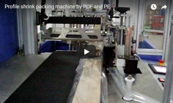
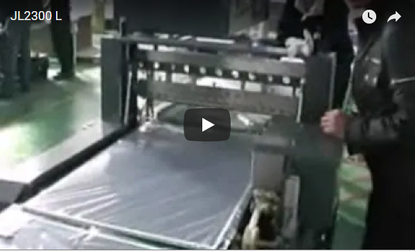
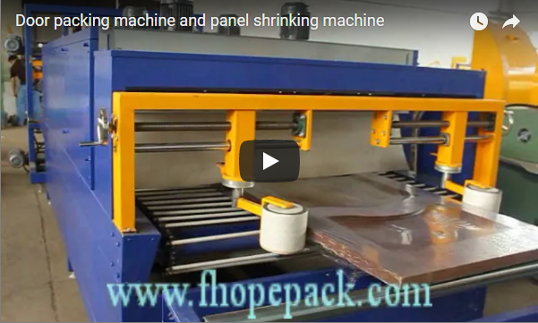
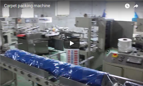
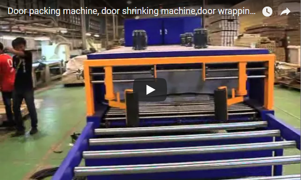
Manual bagging on modern extrusion finishing lines creates immediate bottlenecks and quality hazards. Operators pulling manual plastic sleeves over freshly powder-coated or anodized bundles often drag film across sharp edges, which causes micro-scuffing and tear defects. When bundle lengths reach six to eight meters, manual pacing falls behind the upstream output, leaving finished aluminum vulnerable to moisture and dust.
The automatic aluminum profile bag making and shrinking line wraps extruded bundles in a continuous polyethylene sleeve, seals both ends with a hot knife, and contracts the film inside a convective thermal tunnel. This continuous process encapsulates bundles from 1000 mm up to 8000 mm without surface friction, running up to 15 bundles per minute.
I have spent over 15 years engineering and commissioning automated packaging systems in extrusion mills. Below, I break down the physical line layout, envelope boundaries, thermal setpoints, and selection rules you need before specifying equipment for your plant.
Table of Contents
- What does an automatic aluminum profile bagging and shrinking line do?
- What profile lengths and bundle weights does the standard machine cover?
- Which film and which shrink temperatures fit which finish?
- What should you confirm before requesting a quotation?
- How is the line guarded and interlocked?
- How do you keep it running: maintenance and commissioning?
- What do buyers still ask about aluminum profile bagging?
- Conclusion and Engineering Review
- Related Packaging Systems
- Applicable Standards and References
What does an automatic aluminum profile bagging and shrinking line do?
An automatic bag making and shrinking line converts flat or center-folded polyethylene film rolls into sealed protective sleeves around aluminum bundles before heating them in a shrink chamber. It replaces manual hand-bagging and tape-bundling with a continuous four-station system that synchronizes infeed, motorized sleeve forming, transverse sealing, and convective air shrinking.
[Infeed Conveyor] ──> [Film Unwind & Collar Forming] ──> [Hot-Knife Sealing] ──> [Hot-Air Shrink Tunnel] ──> [Outfeed Buffer]The process begins as the infeed conveyor transfers the bare bundle into the machine. Downstream from the extrusion handling area, the automated film applicator and bag packing line pulls film from an active reel under constant tension. The film passes through an adjustable forming plow that wraps the material loosely over the bundle.
Because the sleeve forms around the profile without axial drag or direct surface shear, sensitive coatings do not rub against the film web. Once the bundle reaches position, a transverse hot knife cuts and seals both ends. The sleeved bundle then enters a recirculating hot-air tunnel where balanced thermal radiation shrinks the film tight against the metal contours.
The integrated line links four synchronized functional modules managed by a master PLC platform:
| Station Module | Engineering Mechanism | Operational Function |
|---|---|---|
| Film Unwinding Station | Constant-tension dancer arm, magnetic powder brake, motorized spool shaft | Feeds PE roll stock (300 to 800 mm roll width) without stretch deformation or web drift. |
| Bag Forming Module | Adjustable forming collar / plow with servo-driven carriage (±2 mm indexing accuracy) | Shapes film web into an axial continuous sleeve surrounding the advancing bundle envelope. |
| Sealing & Cutting Bar | Pneumatic/servo vertical hot-knife bar, Teflon (PTFE) coated, PID thermocouple closed loop | Transverse pulse or hot-blade end-sealing; cuts and fuses bag ends at 120 to 200°C. |
| Shrink Tunnel Chamber | Multi-zone convective hot-air recirculation, centrifugal turbo blower, mesh/roller conveyor | Controlled heat exposure (140 to 180°C) shrinks film evenly across profile contours; conveyor speed 0 to 15 m/min. |
What profile lengths and bundle weights does the standard machine cover?
Standard packaging configurations support profile bundle lengths from 1000 mm to 8000 mm and total bundle weights up to 15 kg. Heavy-duty variants extend line support to 12000 mm architectural beams and carry bundle loads between 25 kg and 50 kg using reinforced, motor-driven conveyor beds.
The machine handles various cross-sectional profiles. It packs single extruded structural bars, rectangular window-frame stacks, and irregular hexagonal mill bundles. All infeed and transfer roller tables use high-density polyurethane (PU) sleeves or non-marking rubber. These materials protect mill finishes, powder-coated layers, and high-gloss anodized surfaces from contact blemishes.
The following technical matrix reflects the core design specifications for this continuous packaging machine series:
| Engineering Parameter | Standard Specification | Custom / Extended Range |
|---|---|---|
| Profile Length Envelope | 1000 to 8000 mm | Extended up to 12000 mm on request |
| Max Bundle Weight | 15 kg (Standard duty) | 25 to 50 kg (Reinforced heavy-duty chassis) |
| Film Compatibility | Monolayer or co-extruded LDPE / LLDPE shrink film | Polyolefin (POF) or Cross-linked PE blends |
| Film Thickness Rating | 30 to 80 µm (Standard profiles) | Up to 100 µm (Heavy industrial profiles) |
| Cycle Rate | 8 to 15 bundles/min (Short profiles ≤ 2000 mm) | 2 to 4 bundles/min (Long profiles 6000–8000 mm) |
| Sealing Temperature Window | 120 to 200°C (PID digital tracking ±2°C) | Adjusted based on line speed and micron rating |
| Shrink Tunnel Operating Temp | 140 to 180°C (Dual-zone air circulation) | Variable velocity convective blowers |
| Tunnel Conveyor Speed | 0 to 15 m/min (Infinitely variable frequency drive) | Synchronized with upstream packaging speed |
| Shrink Chamber Length | 2000 mm standard active heated length | 1500 to 4000 mm options based on line feed rate |
| HMI Recipe Memory | 50+ pre-programmed part configurations | Toolless mechanical changeover < 5 minutes |
| Pneumatic Operating Pressure | 0.5 to 0.8 MPa clean, filtered industrial air | Integrated dedicated air booster unit optional |
| Electrical Power Options | 380 V / 50 Hz (3-Phase + N + PE) | 208 V, 220 V, 440 V, 480 V (50/60 Hz configuration) |
| Chassis Dimensions | 6000 mm (L) × 1200 mm (W) × 1800 mm (H) | Tailored to floor layout and infeed alignment |
| Safety and Norm Compliance | CE Machinery Directive 2006/42/EC, ISO 12100 | UL 508A electrical panel and EAC available |
Which film and which shrink temperatures fit which finish?
Standard industrial applications run low-density polyethylene (LDPE) or co-extruded LLDPE shrink films. The shrink process relies on balanced biaxial film contraction. The baseline film formula requires 50% to 70% shrinkage along the Machine Direction (MD) and 15% to 25% shrinkage along the Transverse Direction (TD).
Heavy structural extrusions, sharp corner geometries, and outdoor storage bundles require cross-linked PE or heavy polyolefin (POF) blends up to 100 µm thick. These films prevent corner puncture during crane handling and transit.
Independent dual-stage thermal regulation maintains product structural stability:
| Thermal Zone | Mechanical Target | Standard Operating Window | Control Precision |
|---|---|---|---|
| Transverse Sealing Bar | Bag end-closure seam fusion | 120 to 200°C | PID monitoring, ±2°C |
| Shrink Tunnel Atmosphere | Uniform sleeve contraction | 140 to 180°C | Forced-air convection, ±2°C |
Thermal Setup Procedure
- Preheat the shrink tunnel heating elements to target operational setpoints between 160°C and 180°C for 15 to 20 minutes before production to ensure uniform convection air distribution.
- Synchronize tunnel conveyor belt speed (0 to 15 m/min) with required bundle dwell time. Thin-walled extrusions require faster transit to avoid heat buildup, while heavy solid bars require longer dwell time for full thermal transfer.
- Check film tension at the unwind dancer arm to prevent web necking or wrinkling before the sheet enters the forming collar.
Because the sleeve forms around the profile without sliding friction, this process protects delicate surface treatments:
- Architectural Framing: Anodized window sills, door frames, structural curtain walls, and thermal-break profiles.
- Powder-Coated Extrusions: High-gloss, matte, and textured polyester powder coatings sensitive to contact abrasion.
- PVDF Coated Facades: Premium architectural panels demanding scratch-free transport protection.
- Industrial and Electrical Components: Inverter heat sinks, busbar trunking, pneumatic cylinder barrels, and structural guide rails.
- Automotive and Solar Aluminum: Roof rails, decorative running boards, and photovoltaic module mounting frames.
If your plant packs extra-long bundles that require spiral wrapping instead of a full shrink sleeve, review the aluminum profile stretch wrapping machine for orbital packaging alternatives.
What should you confirm before requesting a quotation?
Before sending profile drawings to our applications team, gather your product envelope dimensions and plant utility constraints. The machine frame, forming collar width, and heating duct size directly depend on your maximum cross-section and line speed.
Review these primary engineering parameters prior to issuing a technical specification request:
| Evaluation Item | Parameter to Confirm | Engineering Purpose |
|---|---|---|
| Profile Length Range | Minimum and maximum lengths (e.g., 1000 mm vs. 8000 mm) | Determines infeed bed length and shrink tunnel chamber length. |
| Bundle Cross Section | Max Width × Max Height (envelope diagonal) | Fixes the forming plow dimensions and tunnel mouth clearance. |
| Bundle Mass | Heaviest individual load (kg/meter and total kg) | Dictates standard vs. heavy-duty reinforced drive roller spec. |
| Film Formulation | PE, POF, micron thickness, puncture criteria | Determines sealing bar heat wattage and tunnel thermal capacity. |
| Target Output | Required bundles per hour or cycles per minute | Confirms conveyor line speed and pneumatic/servo indexing needs. |
| Plant Facilities | Voltage, supply frequency, available compressed air CFM | Confirms transformer rating and pneumatic header connection. |
| Surface Class | Mill-finish, anodized, PVDF, or coated sensitivity | Establishes soft-touch polyurethane contact roller material spec. |
How is the line guarded and interlocked?
Reciprocating hot cutting knives and heated convection chambers require heavy-duty physical and electrical safety systems. The machine design incorporates multiple safety zones to protect line operators during continuous loading.
- Optical Guarding: Type 4 safety light curtains monitor the infeed entry and outfeed discharge zones, instantly cutting actuator power when an obstruction breaks the optical field.
- Emergency Stop Integration: Hardwired emergency stop pushbuttons sit at the film unwind reel, the bag forming plow, the hot-knife head, and the tunnel discharge area, wired to a PLe safety relay loop per EN ISO 13849-1.
- Thermal Isolation: The heating tunnel uses high-density mineral wool insulation layers inside double-walled steel panels, maintaining outer surface temperatures below standard industrial burn thresholds.
- Maintenance Lockout: Mechanical safety latches hold the vertical knife assembly during blade servicing, while lockable pneumatic dump valves bleed residual line pressure for lockout/tagout (LOTO) protocols.
Specific site guarding layouts and safety categories must always match local plant risk assessments and factory ceiling clearances.
How do you keep it running: maintenance and commissioning?
Scheduled maintenance protects seal integrity, stabilizes heating cycles, and sustains machine availability up to 8000 hours MTBF (Mean Time Between Failures) based on manufacturer baseline operating standards.
Daily Maintenance (End of Shift)
- Clean polymer buildup from the PTFE-coated hot-knife sealing bar using a brass soft-wire brush (never use steel scrapers or hard wire wheels).
- Clean dust and plastic residue from optical photo-sensors and inspect reflector lenses.
Weekly Maintenance
- Check the conveyor drive chain tension and lubricate all drive bearings and pillow blocks.
- Clean the film transport path and wipe tracking rollers to remove airborne electrostatic particles.
Monthly Maintenance
- Calibrate PID temperature thermocouples on the hot-knife sealer and shrink heating zones using an external reference thermometer.
- Inspect pneumatic cylinders, verify rod alignment, and drain compressed air filter bowls.
Factory commissioning typically requires 2 to 4 hours per shift. Line operators learn recipe selection, film roll splicing, manual jog routines, and safety fault resets, enabling line staff to independently run production within half a shift. Toolless mechanical adjustments take under 5 minutes once recipes are established in the HMI.
What do buyers still ask about aluminum profile bagging?
What type of shrink film is best suited for aluminum profile bundles?
Low-density polyethylene (LDPE) shrink film between 30 and 80 µm works best for standard aluminum bundles. For heavier structural loads (25 to 50 kg) or bundles stored outdoors, specify cross-linked polyethylene or heavy polyolefin (POF) up to 100 µm to increase puncture resistance.
How does the machine handle fast changeovers between different profile lengths?
The PLC system stores over 50 part recipes. When operators change profile batches, selecting the part number on the HMI updates optical cut points, conveyor indexing distances, and thermal setpoints. The physical mechanical changeover takes under 5 minutes without tools.
How is bundle surface marring prevented on painted or anodized profiles?
The bag forms around the bundle without sliding friction. Shrinkage occurs only through hot-air convection inside the heating tunnel. In addition, all conveyor contact points feature non-marking rubber or soft polyurethane rollers.
What are the utility supply requirements for this system?
The line runs on a 380 V, 50 Hz three-phase electrical supply (with optional build configurations for 208 V to 480 V, 50/60 Hz). The pneumatic system requires clean, dry compressed air at 0.5 to 0.8 MPa.
Conclusion
Choose a standalone bagging unit if you only need dust protection for cured, non-critical extrusions under 15 kg. Select an integrated bag making and shrinking line when you ship high-gloss architectural bundles, require full moisture encapsulation for open-bed transport, or handle heavy 25 to 50 kg structural packs that require tight structural film containment.
To evaluate your profile line and receive automated packaging layout drawings:
- Submit Profile Data: Email your dimensional mix (minimum and maximum bundle lengths, cross-sections, bundle weights, and target line output) to info@fhopepack.com.
- Receive 2D/3D Concept Layout: Our packaging engineering team delivers a tailored machine layout drawing and performance proposal within 48 hours.
- Site & Utility Verification: We coordinate factory footprint integration, electrical busway connections, and upstream conveyor interfaces prior to machine build.
Explore our engineering options and line integrations directly at www.fhopepack.com.
Related Reading
- Automatic Tape Binding Machine for Box
- Automatic Bag Packing and Shrinking Line
- Aluminum Profile Packaging Machine and Wrapping Line
- Automatic Orbital Stretch Wrapper with Bubble Film Covering for Door Panels
- FHOPE Industrial Packaging Machinery Product Directory
Sources and Standards
- ISO 12100:2010: Safety of machinery — General principles for design, risk assessment and risk reduction. ISO Standard Reference
- EN 415-10:2014: Safety of packaging machines — Part 10: General requirements. NEN / EN Official Standard
- EN ISO 13849-1:2023: Safety of machinery — Safety-related parts of control systems. ISO Standard Reference
- FHOPE Demonstration Archives: Technical operation and cycle demonstration of automatic aluminum bag forming and shrink lines, YouTube.
- FHOPE Aluminum Packaging Line Architecture: Automated handling, stacking, bagging, and bundling system design, FHOPE Aluminum Profile Packing Line.
Last reviewed: 2026-10-09