Packaging mixed runs of long lineal profiles and broad panels on a single packaging line creates constant line stoppages. Wide building boards hit physical frame limits on narrow wrapping stations, while small profile bundles slip and disperse on oversized conveyor beds. Plant teams often try to force every cross-section through one generic machine, only to discover that structural dimension limits and tunnel heat absorption stop production.
Platform selection depends strictly on product cross-section: packages where width plus height totals 400 mm to 900 mm require the MO-900 continuous side sealer, whereas lineal bundles up to 450 mm wide and 150 mm high run on the dedicated profile shrink line to ensure proper bundle stability and seal integrity.
I have set up these horizontal lines on factory floors for over fifteen years. The step-by-step breakdown below explains how continuous sealing functions, how to size each platform to your dimensions, and how heat tunnel velocity controls actual finished output.
Table of Contents
- How does a profile and panel bagging and shrinking line work?
- Which platform fits your product, and what are its specifications?
- How fast can a long product actually run?
- Which film, and how is the seal made?
- What utilities and guarding does the line need?
- What should you confirm before ordering?
- What do buyers still ask about profile and panel shrink lines?
- Conclusion
- Related reading
- Sources
How does a profile and panel bagging and shrinking line work?
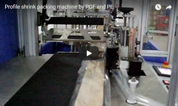
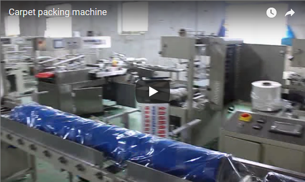
The continuous horizontal wrapping line encloses long products by synchronizing three continuous stages: an automatic infeed that pulls center-folded film around the product with continuous longitudinal side welding, a recirculating convection heat tunnel that shrinks the polymer, and an outfeed cooling conveyor that locks film tension.
The entire wrapping sequence operates in an unbroken inline flow:
- Bagging and Dual-Axis Sealing. The incoming product advances on a variable-speed infeed belt conveyor through the film folder frame. Center-folded Polyethylene (PE) or Polyolefin (POF) film is drawn around the workpiece. A constant-temperature side-sealing knife trims and welds the continuous longitudinal edge. Photoelectric sensors detect the leading and trailing ends, triggering the vertical pneumatic cross-knife to complete the front and tail hermetic seals.
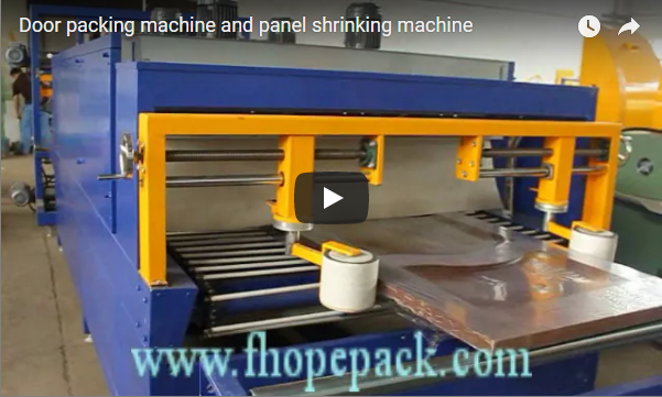
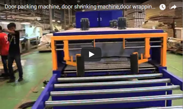
- Controlled Convection Shrinking. A heavy-duty, heat-resistant live roller conveyor transfers the loosely bagged pack through an insulated recirculating air shrink tunnel. Centrifugal blowers direct high-velocity hot air through adjustable top and bottom louvers, softening the polymer and contracting it evenly around the product perimeter without surface blister or dog-ear defects.
- Discharge and Cooling. At the outfeed gravity or powered roller stage, ambient air cooling sets the film tension, stabilizing bundled profiles or composite boards for automatic destacking, palletizing, or manual bundling.

Safety interlocks protect the operating envelope. The heated cutting blades feature physical tunnel guarding, transparent polycarbonate operator shields, and high-visibility warning signage to eliminate pinch and thermal hazard zones during automatic cycles.
Which platform fits your product, and what are its specifications?
Workpiece cross-section determines machine selection because the longitudinal side knife seals continuously along the feed travel, leaving package length unconstrained by mechanical knife assemblies while structural frame width and vertical throat height enforce rigid envelope boundaries.
The dimensional envelopes dictate the base platform:
| Machine Platform | Cross-Section Envelope | Minimum Length | Maximum Height |
|---|---|---|---|
| Side Sealer MO-900 | 400 mm < (Width + Height) < 900 mm | 250 mm | 300 mm |
| Profile Shrink Line | Width ≤ 450 mm, Height ≤ 150 mm | 600 mm | 150 mm |
Engineering Sizing Examples:
- Insulated Architectural Panel (600 mm W × 50 mm H):
Cross-Section Sum = 600 mm + 50 mm = 650 mm. This profile falls directly inside the MO-900 operational band (400–900 mm). The wide conveyor bed and 1,100 mm transverse seal bar ensure adequate lateral clearance. - Extruded Aluminum Bundle (200 mm W × 100 mm H):
Cross-Section Sum = 200 mm + 100 mm = 300 mm. While below the MO-900 structural envelope, this dimension aligns with the compact Profile Shrink Line, which provides dedicated lateral guiding rollers to prevent profile bundle dispersion during high-speed transit.
Before equipment commissioning, our engineering team evaluates both the maximum profile diagonal and the minimum bundle rigidity to prevent material sag across conveyor transition bridges.
Side Sealer MO-900 Specifications (Panels & Wide Formats)
| Parameter | Specification | Engineering Standard |
|---|---|---|
| Sealing Architecture | 4-side fully closed enclosure | Continuous side seam + vertical cross weld |
| Cross-Seal Knife Span | 1,100 mm | Teflon-coated serrated alloy bar |
| Maximum Conveyor Velocity | 15 m/min | VFD inverter-controlled |
| Compatible Films | Single-wound PE (30–80 µm), POF (12–25 µm) | Center-folded roll stock |
| Installed Connected Load | Sealer: 2.5 kW; Shrink Tunnel: Max. 28 kW | 3-phase electric heating bank |
| Conveyor Passline Height | 850–900 mm (adjustable) | Heavy-duty leveling mounts |
| Total System Mass | 2,000 kg | Structural steel frame |
Profile Shrink Line Specifications (Narrow Lineals & Extrusions)
| Parameter | Specification | Notes |
|---|---|---|
| Sealer Frame Dimensions | 1,850 × 980 × 1,450 mm | L × W × H |
| Sealer Conveyor Speed | Up to 20 m/min | Independent servo/inverter drive |
| Tunnel Chamber Size | 1,500 × 550 × 300 mm | Usable thermal window (L × W × H) |
| Tunnel Conveyor Speed | 0–10 m/min | Variable thermal dwell control |
| Shrink Tunnel Dimensions | 1,900 × 800 × 1,380 mm | Insulated double-wall enclosure |
| Conveyor Surface | High-friction synthetic belt | Non-marking surface for fine finishes |
How fast can a long product actually run?
Overall packaging throughput on long workpieces depends entirely on the downstream heat tunnel dwell velocity rather than the infeed sealer drive, because plastic film requires adequate exposure time inside the heated convective air chamber to shrink uniformly.
Cycle calculations follow this principle:
Cycle Calculation Principle:
Total Pitch Length = Product Length (L) + Inter-Pack Spacing Gap (G)
Cycle Time per Unit = (L + G) ÷ V_tunnel
Net Throughput = 60 ÷ Cycle Time per Unit
Where:
L= Workpiece length in meters.G= Required spacing gap (typically 0.2 m to 0.4 m to allow full vertical stroke and dwell of the cross-seal knife).V_tunnel= Heat tunnel conveyor velocity (operating between 0 and 10 m/min).
Operational Output Benchmark (6.0-Meter Profiles):
- Governing Tunnel Velocity: Set at 8.0 m/min for heat transfer into 50 µm PE film.
- Effective Pitch:
Effective Pitch = 6.0 m + 0.3 m = 6.3 m per package cycle. - Calculated Production Rate:
Production Rate = (60 min/h × 8.0 m/min) ÷ 6.3 m/piece = 76 pieces/hour. - Mechanical Upper Bound: At maximum tunnel velocity (10.0 m/min) with lightweight POF film, ceiling output approaches
Ceiling Rate = (60 × 10.0) ÷ 6.3 ≈ 95 pieces/hour.
Real-world line speed depends on the thermal mass of the workpiece, film gauge, and target shrinkage uniformity. Full factory acceptance testing validates thermal dwell times for your specific film gauge.
Which film, and how is the seal made?
Long products demand consistent film tension and rigid thermal control during sealing. The sealing system combines continuous longitudinal welding with synchronized vertical cutting:
- Continuous Side-Knife Assembly: A dedicated high-precision, constant-temperature cartridge heater powers the longitudinal side seal wheel. Operating without cycle-pause interruptions, it eliminates edge flashing and makes packaging length unconstrained.
- Pneumatic Cross-Cut Bar: Guided by precision linear bearings, the cross-seal bar delivers uniform vertical clamping pressure across its full 1,100 mm span. Solid-state PID control prevents wire carbonization and weak weld seams.
- Multi-Axis Optoelectronic Detection: Dual arrays of horizontal and vertical optical sensors detect leading and trailing workpiece edges. This ensures instantaneous cross-cut actuation on ultra-thin sheet goods down to 2 mm thickness or non-standard profiles.
- Tension-Controlled Trim Rewinder: Edge scrap film is automatically guided and tightly coiled by an independent torque-controlled rewind motor, maintaining consistent lateral web tension.
- Rapid Dimension Changeover: Product width and height adjustments are executed in under three minutes via calibrated manual hand wheels and lead screws.
System automation uses an industrial-grade PLC paired with multi-channel digital PID temperature control. This design maintains thermal sealing consistency within ±1.5°C across operating shifts.
What utilities and guarding does the line need?
The heat shrink tunnel represents the primary electrical load on site. Facilities must verify local transformer feeder capacity before installation.
| Utility / Service | Side Sealer MO-900 Line | Narrow Profile Shrink Line |
|---|---|---|
| Electrical Service | 380 V / 400 V AC, 3-Phase, 50/60 Hz | 380 V AC, 3-Phase, 50/60 Hz (Customizable) |
| Pneumatic Supply | 0.5–0.7 MPa (5.0–7.0 bar), clean dry air | 0.6–0.8 MPa (6.0–8.0 bar), dry regulated air |
| Total Peak Draw | 30.5 kW (Sealer 2.5 kW + Tunnel 28 kW) | 16.0–22.0 kW (Configuration dependent) |
Safety and Compliance Architecture:
- Machinery Safety Standards: Systems reference safety design guidelines under ISO 12100:2010 and EN 415-10:2014.
- Physical Guarding: Guarded infeed apertures prevent accidental hand access into the cutting zone.
- Emergency Circuitry: Dual-channel Category 3 / PL d emergency stop circuits disconnect pneumatic valve manifolds and isolate heating banks upon actuation.
- Site Guarding Boundary: Final safety fences and interlock integration must reflect plant-specific risk assessments.
What should you confirm before ordering?
Before requesting a layout drawing or equipment quotation, collect and verify these parameters:
- Cross-Sectional Envelope: Confirm minimum and maximum product Width (
W) and Height (H). - Product Length Distribution: Minimum length (≥ 250 mm for MO-900) and maximum span to size floor conveyors.
- Film Specification: Polymer base (PE vs. POF), film gauge (microns), and center-fold roll unwind diameters.
- Throughput Objectives: Required pieces per hour to verify tunnel speed using the pitch formula.
- Surface Sensitivity: Need for anti-scratch belt coatings, felt-lined guides, or rubberized tunnel rollers.
- Plant Utilities: Availability of 380–480 V 3-phase power drop and dry compressed air (≥ 0.6 MPa).
What do buyers still ask about profile and panel shrink lines?
Is there any theoretical restriction on maximum product length?
No. Because the longitudinal side knife seals continuously while the workpiece advances, workpiece length is unlimited. The only constraints are physical building space, roller table extensions, and raw material support fixtures. Minimum stable handling length on the MO-900 is 250 mm.
Why does a 600 mm wide by 50 mm thick panel require the MO-900 rather than the Profile Line?
The panel’s 600 mm width exceeds the physical infeed width limit (450 mm) of the Profile Shrink Line. Its combined sum of 650 mm falls squarely within the MO-900 operational window (400 mm to 900 mm).
How does the system switch between different bundle dimensions?
Operators rotate calibrated mechanical hand wheels to adjust the infeed guiding fences, film inversion triangle, and cross-cut head height. Electrical photo-eyes automatically adjust length sensing on the fly via the PLC program.
What is the primary bottleneck determining line throughput?
Line bottleneck is tunnel heat absorption. While the infeed sealer can index up to 15–20 m/min, the pack must spend adequate dwell time inside the thermal chamber. Cycle calculation follows the tunnel speed formula detailed in the line speed section.
Can the line seal both Polyethylene (PE) and Polyolefin (POF) films?
Yes. The system handles both film chemistries. PE film requires heavier heating elements and longer tunnel chambers, whereas POF operates with thinner gauges, lower seal temperatures, and higher visual transparency.
Conclusion
Select your equipment using this rule: if product width plus height totals 400 mm to 900 mm, or individual panel width exceeds 450 mm, install the MO-900 side sealer platform. If you run lineal extrusions up to 450 mm wide and 150 mm high, select the dedicated profile shrink line. If your facility runs both products, size the main chassis for your widest panel and apply recipe-based guide adjustments for narrow extrusions.
Our engineering team delivers custom layout integration drawings and factory performance quotes through a rapid 3-step technical workflow:
- Submit Factory Parameters: Send your product cross-sections, minimum/maximum lengths, surface sensitivity requirements, and target units/hour to info@fhopepack.com.
- Engineered Proposal in 48 Hours: Receive a layout proposal, including infeed/outfeed conveyor spans, electrical consumption profile, and cycle time simulations.
- Application Verification & FAT: Ship raw sample profiles to our testing facility for real-world film shrinkage trials, weld pull tests, and optical inspection before equipment sign-off.
Visit www.fhopepack.com to review our complete range of profile packaging lines and motion side-sealing systems.
Related reading
- Side Sealer Shrinking Machine MO-900 Technical Overview
- Aluminum Profile Shrink Wrap Packaging Machine
- Industrial Shrink Wrapping Machinery Index
- Fully Automated Packaging Lines for Long Products
- Custom Heavy-Duty Wrapping Solutions
Sources
- Side sealer technical criteria, sealing architecture, and electrical utility specifications: MO-900 Industrial Shrinking Machine
- Profile line dimensions, conveyor configurations, and speed capabilities: Aluminum Profile Shrink Wrapping Systems
- Line mechanical operation and motion kinematics: Profile and Panel Bagging & Shrinking System Demonstration
- Safety and machinery standards: ISO 12100:2010 Safety of Machinery, EN 415-10:2014 Safety of Packaging Machines
Last reviewed: 2026-10-03