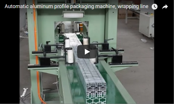
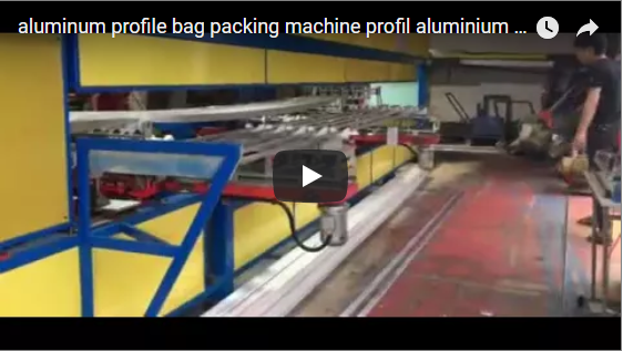
Executive summary High-grade extruded aluminum profiles—particularly architectural sections with anodized, electrophoretic, or powder-coated finishes—are highly susceptible to surface scratching, denting, and mechanical deflection during manual drag handling and unsecured transport. The integrated packing line analyzed below coordinates motorized roller transfer, profile alignment on cushioned support cradles, centralized PLC/HMI line control, and bundle end-finishing with protective taping and identification. Sizing the system requires aligning your shift extrusion output, target bundle weight, and unit profile cycle time to prevent the packaging cell from becoming a downstream extrusion bottleneck.
Table of Contents
- Line Overview and Engineering Layout
- Station-by-Station Process Flow
- Line Pace and Bundles-per-Hour Calculation
- Electrical Controls and Machine Safety
- Engineering Selection Checklist for Aluminum Profile Lines
- Frequently Asked Questions
- Next Step: Engineering Layout and Proposal
- Related Systems and Reading
- Standards and Technical References
Line Overview and Engineering Layout
In industrial aluminum extrusion facilities, the secondary packing process must bridge the gap between continuous upstream extrusion/aging and downstream warehouse logistics. Transporting loose or partially manual-bundled profiles across production bays introduces physical friction, leading to irreversible surface scuffs and bundle destabilization under transport vibration.
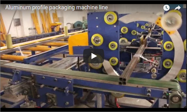
The layout deployed here features heavy-duty structural orange steel frames equipped with non-marking, polyurethane-sleeved white rollers. This ensures that soft 6000-series structural alloys never experience bare metal-to-metal contact during longitudinal travel. Parallel guide rails maintain bundle tracking, preventing lateral slip and edge binding.
The line architecture bridges semi-automated handling with automated conveyance:
- Infeed & Outfeed Conveyors: Dual motorized roller decks dedicated to transferring raw assembled bundles and evacuated finished packs.
- Manual Layering & Alignment Deck: Heavy-duty structural supports (cradles) where operators inspect, arrange, and interlock hollow profiles into uniform geometric bundles.
- Master Control Center: Ergonomically isolated operator console backed by an industrial yellow power distribution cabinet, running synchronized variable-frequency drives (VFDs).
- Finished Staging Racks: Heavy-duty cantilever sorting buffers holding end-taped, labeled, and protective film-wrapped master bundles ready for overhead crane or forklift retrieval.
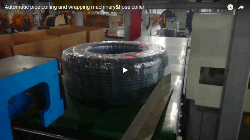
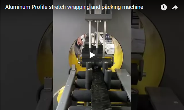
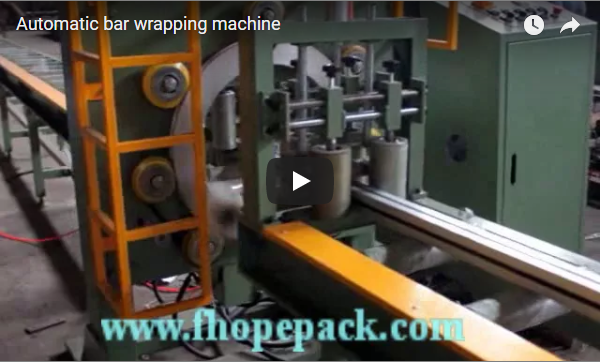
Note on Configuration Scope: While this specific setup highlights roller transport, manual alignment stations, and master control, automated spiral stretch wrapping, paper interleaved wrapping, and master polyethylene sleeve bagging modules can be directly integrated inline into the conveyor sequence without altering the control architecture.
Station-by-Station Process Flow
The workflow balances continuous mechanical transfer with precision manual assembly. The table below outlines the operational sequence recorded during baseline field operation.
| Station / Sequence | Engineering Function & Material Action | Baseline Footage Reference |
|---|---|---|
| 01. Infeed Conveyance | Polyurethane-sleeved motorized rollers convey assembled profile batches forward with controlled acceleration to eliminate inter-profile slippage. | ~30–54 s |
| 02. Desk Operation | Primary operator monitors infeed tracking, line interlocks, and conveyor segment indexing via the main desk control panel. | ~60–66 s |
| 03. Profile Support & Handling | Technicians position individual hollow profiles onto non-abrasive orange support cradles for alignment, layering, and intermediate spacer insertion. | ~72–120 s |
| 04. Central Line Dispatch | Main electrical cabinet controls variable line speeds, safety circuits, and transfer pneumatic solenoids across adjacent decks. | ~126–156 s |
| 05. Finished Bundle Accumulation | Master bundles—secured with reinforced tape, structural end wraps, and itemized tracking barcodes—are staged on cantilever holding racks. | ~162–174 s |
By shifting product transport loads entirely onto the powered roller system, physical strain on technicians is restricted to horizontal profile alignment and bundle indexing. Perimeter tape and stretch-film containment around bundle ends secure the profile arrangement against longitudinal skewing and protect against shear displacement during transport.
Line Pace and Bundles-per-Hour Calculation
To properly size a packaging cell, line speed must be derived directly from the extrusion press throughput. A packaging line that cycles slower than the hot extrusion run causes run-out table blockage, forced press downtime, and lot accumulation.
Worked Engineering Example
The following dataset demonstrates how to determine your allowable cycle budget per bundle:
| Operational Parameter | Baseline Parameter Value | Calculation Formula |
|---|---|---|
| Target extrusion output per shift | 12,000 kg (12 metric tons) | Baseline input |
| Nominal finished bundle weight | 500 kg | Customer packaging spec |
| Bundles required per shift | 24 bundles | 12,000 kg ÷ 500 kg = 24 |
| Net operating shift duration | 8.0 hours (480 minutes) | Single plant operational shift |
| Target line throughput rate | 3.0 bundles / hour | 24 bundles ÷ 8 h = 3 |
| Available cycle time per bundle (T_cycle) | 20.0 minutes / bundle | 60 min ÷ 3 bundles = 20 min |
Engineering Implications on Station Balancing
If a customer packaging spec demands a master bundle of 500 kg containing 50 individual hollow profiles (10 kg each), handling profiles manually onto support arms at a rate of 15 seconds per profile consumes:
50 profiles × 15 s = 750 s (12.5 minutes)
Adding 3.0 minutes for longitudinal roller conveyance and 2.5 minutes for end taping and barcoding yields an effective gross cycle time of 18.0 minutes. This sits safely within the 20.0-minute ceiling (18.0 min ≤ 20.0 min).
However, if output jumps to 18 tons/shift (demanding T_cycle ≤ 13.3 minutes), manual loading will choke the cell. In that operating window, automated layer stackers or powered bundling arms must be integrated to recover throughput margins.
Electrical Controls and Machine Safety
Handling bundles weighing between 500 kg and 2,000 kg over moving rollers creates severe pinch-point, entrapment, and crush risks. Safety integration must follow international machine safety standards:
- Conveyor Interlocking: Operators must never stage or adjust individual profiles while a roller segment is powered. Motorized sections must use zone-specific photoelectric sensors tied to dual-channel safety relays. When an operator breaches an active manual-staging zone, the corresponding drive circuit must initiate an immediate category 0 or 1 stop (in accordance with ISO 13850).
- Physical Clearance: Operator foot positions must maintain strict clearance distances from powered rollers, idlers, and hydraulic scissor transfer arms to prevent limb entrapment under ISO 13857.
- Control Architecture: Emergency stop (E-stop) pushbuttons must be mounted directly on the local pendant station, the master yellow electrical cabinet, and along conveyor perimeter guard points.
- Regulatory Harmonization: For systems destined for European Union (CE) markets, the integrated line must pass risk assessments per ISO 12100:2010 and satisfy the essential health and safety mandates of EN 415-10:2014 (General requirements for packaging machines) and low-voltage/EMC machinery directives.
Engineering Selection Checklist for Aluminum Profile Lines
When engineering a custom profile wrapping and handling cell, verify the following mechanical boundaries before finalizing layout prints:
- Profile Geometry: Maximum and minimum lengths (e.g., 2,500 mm to 7,500 mm), cross-sectional envelope dimensions, wall thickness, and weight per meter.
- Surface Sensitivity: Bare mill finish, electro-polished, silver/color anodized, powder-coated, or wood-grain transfer (dictates roller sleeve material: Polyurethane, Ultra-High-Molecular-Weight Polyethylene (UHMW-PE), or vulcanized rubber).
- Master Bundle Dimensions: Cross-sectional configurations (square, hexagonal, rectangular; e.g., 300 × 300 mm up to 800 × 800 mm) and maximum bundle payload (e.g., 2,500 kg).
- Packaging Material Stack: Single-layer stretch wrapping, continuous PE tube bagging, paper interweaving, crepe paper external wrapping, or fiberglass-reinforced filament end taping.
- Labeling & Traceability: Barcode/QR content, auto-print-apply requirements, and direct application to exposed profile ends versus external outer film.
- Plant Floor Constraints: Overhead crane clearance, floor loading capacity, transfer car rail pathways, and dedicated forklift staging buffer bays.
Engineering FAQ
Q: How is the required line cycle time calculated from extrusion data?
A: Divide your gross shift output by the design bundle weight to find total bundles needed, then divide your net shift hours by that bundle count. For example: 12,000 kg ÷ 500 kg = 24 bundles per shift. Over an 8-hour shift, 24 ÷ 8 = 3.0 bundles per hour, giving an available cycle time of 20 minutes (1,200 seconds) per bundle.
Q: How does the conveyor line prevent scuff marks on high-gloss or powder-coated aluminum?
A: Steel roller cores are fully sleeved in high-density polyurethane (PU) or UHMW sleeves. This completely eliminates steel-on-aluminum friction and prevents metallic contamination or gouging of finished architectural surfaces during longitudinal conveyance.
Q: Why are the bundle ends taped and labeled prior to warehouse discharge?
A: Profile ends bear the highest concentration of shear dynamic loads during acceleration, braking, and rough truck transport. Filament tape applied across profile perimeters locks the structural arrangement and prevents internal hollow profiles from sliding out (“telescoping”). End-applied labels ensure identification remains visible when bundles are stacked side-by-side in high-density cantilever storage racks.
Q: Can automated wrapping, spiral wrapping, or bagging modules be combined with this line?
A: Yes. The system runs on a modular PLC architecture (Siemens S7 or Mitsubishi iQ-R series). Automated orbital stretch-film wrapping rings, master bundle sleeve-bagging machines, or automated strap applicators can be dropped into the motorized conveyor path without redesigning the main infeed/outfeed transport logic.
Q: What profile lengths can this specific line design accommodate?
A: Standard conveyor frames process profile bundles between 3,000 mm and 7,500 mm. For extended architectural extrusions (up to 12,000 mm) or short components (down to 1,500 mm), roller center-to-center distances (pitch) and additional intermediate support drop-arms are engineered specifically to prevent profile sag or inter-roller drops.
Next Step: Engineering Layout and Proposal
We design, build, and commission custom packaging, handling, and wrapping equipment matched to your plant’s extrusion press rate.
- Submit Plant Layout & Profile Specs: Forward your profile cross-section prints, length range, bundle dimensions, and target shift tonnage directly to info@fhopepack.com.
- Receive 3D Layout & Technical Proposal: Within 48 hours, our packaging engineering team will deliver a customized line footprint (DWG/PDF), mechanical station assignments, and calculated line throughput data.
- Conduct Line Audit & Integration Review: Coordinate an engineering review with our project managers to verify conveyor deck heights, electrical busbar tie-ins, safety guarding zones, and warehouse discharge rack placement.
Related Systems and Reading
- Industrial Aluminum Extrusion Handling and Packing Solutions
- Automated Horizontal Aluminum Profile Wrapping & Stacking Lines
- High-Speed Heavy-Duty Bundle Strapping and Tying Stations
Standards and Technical References
- Machine Content & Field Specifications: FHOPE Mechanical Engineering Group, Review Cycle 2026-10-04.
- Machinery Safety Standard: ISO 12100:2010 – Safety of machinery — General principles for design — Risk assessment and risk reduction.
- Packaging Equipment Safety Standard: EN 415-10:2014 – Safety of packaging machines — Part 10: General requirements.
- Emergency Stop Principles: ISO 13850:2015 – Safety of machinery — Emergency stop function — Principles for design.
- Field Reference Demonstration: FHOPE Official Packaging Demonstration on YouTube.
Last reviewed and engineering verified: 2026-10-04