Executive summary A V-cradle coil upender carries the coil through the turn while the floor around it stays clear. Our FPCT range is specified for 3, 5, 10, or 20 t, configured per project, and turns coils through 90 degrees as standard. Below: tilt control, ratings, safety features and the practice that keeps the swing area empty.
Table of Contents
- What a V-cradle upender does
- How the tilt keeps the load under control
- Rated capacity, speed and power
- An illustrative coil load calculation
- Controls and safety features
- Safe practice around a moving cradle
- Engineering FAQ
- RFQ checklist
- Next step
- Related reading
What a V-cradle upender does
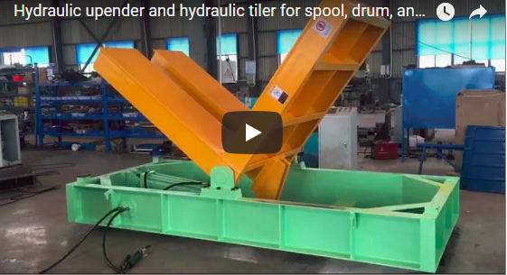
A V-cradle upender rests the coil in an angled seat. During the turn, the legs of the V carry the coil face and the coil outside diameter, so the load rides on shaped supports instead of balancing on a single edge. The coil axis moves from horizontal to vertical, or back the other way, with the cradle doing the work instead of a sling.
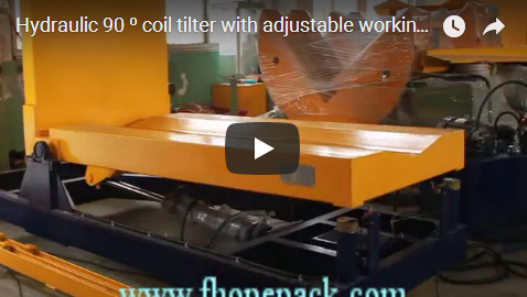
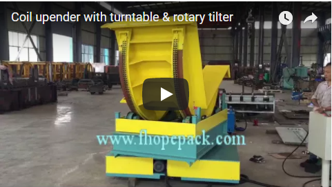
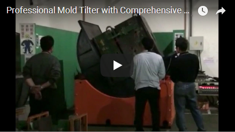
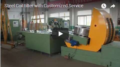
The clip opens on other upenders standing in the workshop, including a yellow and blue V-cradle unit without a load. The main machine then comes into view: a yellow V-shaped cradle on a green base, a toothed arc on its side, a coil resting in the cradle. Workers in hard hats stand around it, and a person crouches at floor level beside it and a neighbouring blue unit.
Nothing in the picture makes the cradle’s motion clear at that moment. The footage depicts factory commissioning; operational installations require hard guarding, perimeter interlocks, and marked swing zones.
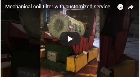
After a cut to a different hall, the same type of cradle turns a large coil of dark corrugated hose. The coil ends up sitting on the other leg of the V, and a person stands some distance behind the machine. The load on screen is a hose coil, and its weight and size cannot be read from the picture. That is why a machine rating should come from your coil drawing rather than from a clip.
How the tilt keeps the load under control
During the turn, the centre of gravity travels over the pivot, so the drive has to hold the load at every angle. A self-locking gear or a brake does that job; the cradle stays where it is put, with the motor on or off. Our FPCT coil upender is specified for 90-degree turning, and 180-degree rotation is available, configured per project.
While the cradle moves, the swing area in front of it is kept empty. Loading and unloading happen with the cradle stopped, so the coil is set down or picked up from a machine that is holding still.
Rated capacity, speed and power
Our FPCT range is specified for max loads of 3, 5, 10, or 20 t, 50-90 s tilting for 3 and 5 t, 60-90 s for 10 t and 60-100 s for 20 t, and 1.3 to 7.8 kW motor power, configured per project.
| Max load | Tilting speed (s) | Motor power |
|---|---|---|
| 3 t | 50-90 s | 1.3 kW |
| 5 t | 50-90 s | 2.0 kW |
| 10 t | 60-90 s | 4.5 kW |
| 20 t | 60-100 s | 7.8 kW |
Range values for the FPCT coil upender and tilter, configured per project.
An illustrative coil load calculation
Drawing numbers beat guesses, so here is an illustrative example, not a rating. Take a solid steel coil with a 1.5 m outside diameter, a 0.508 m bore and a 1.2 m width. With steel at 7850 kg/m³ and pi at 3.1416:
m = 7850*3.1416/4*(1.5**2-0.508**2)*1.2 ≈ 14737 kg
This treats the coil as a solid ring, so it is an upper bound: wire rod and hose coils carry voids and come in lighter. Send your real coil drawing and the machine is rated for your load, configured per project.
Controls and safety features
The gear motor provides the power drive and the inverter controls the speed. The machine can be stopped at any angle even if the power is turned off, and an emergency stop with a position lock function holds the cradle against rotation. On the machine itself, displacement limiters and limit sensors define the end positions of the tilt. The layout keeps the operator away from the coil turning position, which removes the reach-and-flip step where hand injuries happen.
The standards that apply depend on the destination market. For CE markets, ISO 12100 sets the risk-assessment method and EN 415-10 covers the safety of packaging machines of this kind.
Safe practice around a moving cradle
Nobody belongs in the swing area while the cradle moves. Never reach into the swing area to free a coil, straighten wrapping or retrieve packaging; stop the machine and let the cradle settle before your hands go anywhere near the load. For any work at or near the load, stop the machine and follow your site’s isolation procedure before anyone steps in.
The frames in the clip place people close to the machine. Treat that as a prompt to plan walkways, barrier lines and the operator position around the cradle, not as a worked example of good behaviour.
Engineering FAQ
Q: What loads does a V-cradle upender take? A: Coils ride on their face and outside diameter in the V seat, so the shape suits steel strip, aluminium, copper and hose or wire coils. The exact rating is chosen per project.
Q: How far does the cradle rotate, and how fast? A: Standard units turn the load through 90 degrees; 180-degree rotation is available as an option. Tilting speed ranges from 50 to 100 seconds per cycle depending on machine capacity (3, 5, 10, or 20 t).
Q: What holds the coil mid-turn? A: Mid-turn holding comes from the drive itself: a self-locking gear or a brake keeps the cradle at whatever angle the operator leaves it, power on or power off.
Q: Which standards should a buyer check? A: For CE supply, the risk-assessment method is ISO 12100 and EN 415-10 covers packaging machines of this kind; other markets follow their local equivalents.
Q: Can the tilt be interrupted partway? A: Yes. Power can be cut and the cradle rests where it stands, with displacement limiters and limit sensors marking the end positions.
RFQ checklist
- Coil outside diameter, bore and width, with a drawing if available
- Coil weight, or the material so we can calculate it
- Eye direction before and after the turn
- Floor space, approach direction and lifting gear at the installation site
- Destination market, so the applicable safety standards are applied
Next step
- Submit your layout drawing.
- Receive a proposal within 48 hours.
- Book a site survey.
Email info@fhopepack.com with your coil sizes and floor plan, and we will take it from there.
Related reading
- Multipurpose & Automatic Coil Tilter with Slide Table
- Coil Tilter and Upender: 90° Turn of a Palletised Coil
- Large and Long Coil Upenders in Real-World Operation
Sources
- FPCT coil upender and tilter — our machine class for this post
- The FHOPEpack video embedded above
- ISO 12100 and EN 415-10
Last reviewed: 2026-10-06