Executive summary The footage shows a tilting machine handling loads on a platform in a factory. Our equivalent solution is a hydraulic upender and tilter line rated for a load envelope of 100 mm to 3000 mm and a capacity of 15 t, configured per project. This guide covers how the machine works, what loads it handles, and how to specify one.
Table of Contents
- What the footage shows
- Why production loads need to be rotated
- What an upender or tilter does
- How a hydraulic tilter works
- Load types you can handle
- Our equivalent solution and specification ranges
- Installation and floor space
- Controls and safety
- Selection checklist
- Engineering FAQ
- Next step
- Related reading
- Sources
What the footage shows
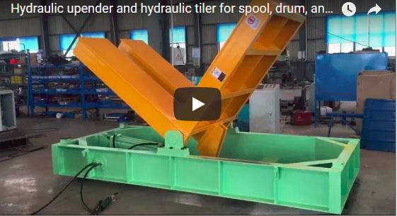
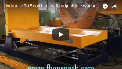
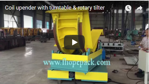
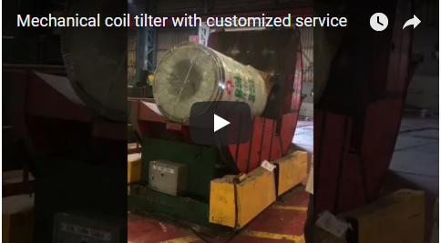
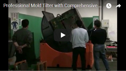
The video is a walk-around of a tilting machine in a factory. A stack of cardboard boxes rests on a pallet on the machine platform while an operator stands beside it at the control panel. The load sits on the platform through most of the footage.
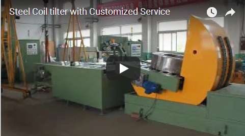
A tilting conveyor and a tilting hopper appear in separate shots. A yellow safety cage surrounds the equipment in several frames. The camera keeps a wide side view, so you can follow the platform and the guarding at the same time.
Why production loads need to be rotated
Many products travel through a plant lying flat. Moulds, die sets, sheet stacks and compact assemblies all reach a point where they must come up on edge. The reason can be strapping, wrapping, edge protection, or loading into a press or a machining fixture.
Turning such a load with slings and an overhead crane is slow and hard on the product edges. A dedicated tilting machine does the job with the load resting on a platform, so the package stays intact and the operator stays clear of the swing.
What an upender or tilter does
An upender, also called a tilter or load inverter, rotates a load around a horizontal axis. The load is placed on a platform or in a cradle. The table tilts through its rotation angle, and the load leaves the machine standing on the face you need.
The rotation is powered and guided. The load does not swing, and the cycle is repeatable from one shift to the next.
How a hydraulic tilter works
The platform is moved by hydraulic cylinders fed from a hydraulic power unit. In our range the motor is rated at 2.5 kW and the hydraulic system at 4.5 kW, each configured per project.
The cylinder on our model has an OD of 100 mm. The maximum working pressure is 14 MPa, configured per project. Pushbuttons or selector switches on the operator station control the hydraulic valves via the PLC, so the operator starts and runs the cycle from a safe position outside the tilt envelope.
Load types you can handle
Typical loads are moulds, die sets, steel and stainless sheet stacks and compact stampings. Because the rated height runs to 350 mm, the envelope is engineered for flat sheet packs and compact dies; tall pallet stacks fall outside the rated range. Our model is specified for a load envelope of 100 mm to 3000 mm in length, 250 mm to 1850 mm in width and 10 mm to 350 mm in height. The capacity is 15 t, configured per project.
A hydraulic coil upender variant for 10 t belongs to the same family. The contact surfaces are lined so that sheet edges and finished surfaces are not scored during rotation.
Our equivalent solution and specification ranges
The machine in the footage is not our unit. Our equivalent solution is a hydraulic upender and tilter line for moulds, die sets, sheet stacks and compact loads. Full specification ranges: steel sheet upender.
| Item | Our specification, configured per project |
|---|---|
| Load envelope | 100 mm to 3000 mm x 250 mm to 1850 mm x 10 mm to 350 mm |
| Capacity | 15 t |
| Maximum working pressure | 14 MPa |
| Motor | 2.5 kW |
| Hydraulic system | 4.5 kW |
| Hydraulic cylinder OD | 100 mm |
| Machine size | 3000 x 2200 x 2600 mm |
| Coil upender variant | 10 t |
Every unit is configured per project. Table size, rotation angle, cylinder layout and guarding are matched to your product and your floor plan.
Installation and floor space
The machine size in our range is 3000 x 2200 x 2600 mm, configured per project. Plan a level foundation with clearance for the tilted platform to sweep through its full arc.
Leave room at the front for load entry and at the side for the control panel. Keep the guarding and the safety fence outside the sweep of the table.
Controls and safety
The footage is a camera walk-around, not a procedure. Guarding and a control position away from the load keep the operator clear of the tilt zone during operation. Before any work at the load, stop the machine, isolate it and apply your site’s lock-out procedure. Never reach into the tilt zone while the platform is moving.
The standards that apply depend on the destination market. For CE markets, ISO 12100 sets the risk-assessment method and EN 415-10 is cited for tilting and upending equipment of this kind. Apply the same logic to guarding, hold-to-run controls and the layout of the fence.
Selection checklist
- Load envelope and weight — length, width, height and mass against the ranges above.
- Rotation angle and loading direction — which face the load must land on.
- Floor space — machine footprint plus the full sweep of the tilted platform.
- Power supply and hydraulic ratings — matched to the project documentation.
- Guarding and controls — fence layout, control position and stop points.
- Layout drawing — sent in for the proposal and the site survey.
Engineering FAQ
Q: What load sizes can the machine take? A: The envelope runs from 100 mm to 3000 mm in length, 250 mm to 1850 mm in width and 10 mm to 350 mm in height. Capacity is 15 t, each configured per project.
Q: How fast does the platform tilt? A: Tilt speed depends on the rotation angle and the hydraulic flow set for your project. Cycle time is controlled through pump displacement and flow control, so each unit is tuned to its load; the cycle time in seconds is confirmed with your layout drawing at the proposal stage.
Q: Which loads are the best fit? A: Flat sheet packs, compact dies, stampings and compact assemblies sit comfortably within the 10 mm to 350 mm height envelope. Tall pallet stacks exceed the rated height, so discuss them with engineering before ordering; loads can also be packed on edge to stay within the envelope.
Q: Which standards apply? A: For CE markets the risk assessment follows ISO 12100, and EN 415-10 covers tilting and upending equipment. Destination-market requirements are confirmed at the proposal stage.
Q: Do you build a version for coils? A: Yes. A hydraulic coil upender variant for 10 t belongs to the same family. Cradle geometry is matched to the coil width and eye orientation.
Next step
We size an upender or tilter in three steps:
- Submit your layout drawing with the load envelope, weight and rotation angle, to info@fhopepack.com.
- Receive a proposal within 48 hours, including the platform configuration and the guarding layout.
- Book a site survey so we confirm the loading path, the floor space and the control position at your station.
Related reading
- Steel Sheet 180-Degree Turning and Upending Process — sheet stacks turned and upended on a powered table.
- Hydraulic Drywall Sheet Upender: 180-Degree Sheet Turner — a hydraulic sheet turner in operation.
- Multipurpose & Automatic Coil Tilter with Slide Table — the tilter principle applied to coils.
Sources
- [the video on YouTube]
- Steel sheet upender product page (specification ranges), fhopepack.com
- FHOPE engineering team, 2026-10-07
Last reviewed: 2026-10-07