Executive Summary
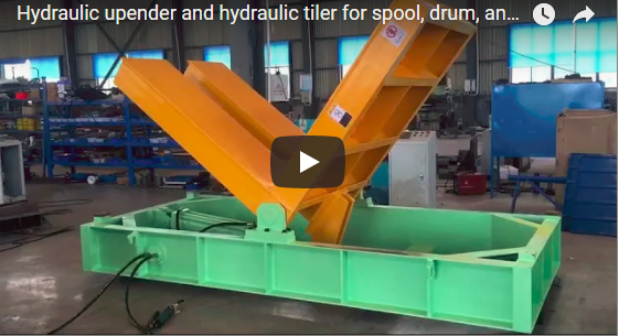
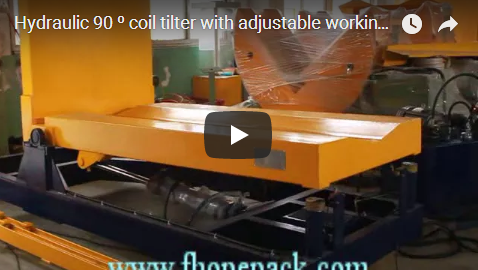
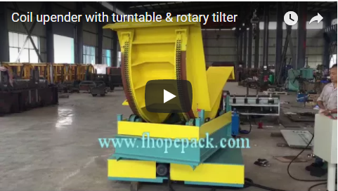
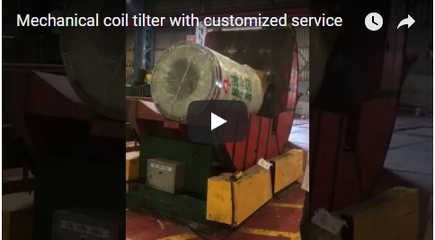
A multipurpose automatic coil tilter with a slide table combines linear transfer and angular reorientation in one machine. The table runs out beyond the cradle envelope, so a forklift, crane C-hook or plant conveyor stages the load in open space; the table then retracts the load into the tilting cradle for a 90° upending or 180° turnover. The configuration suits steel coils, wire spools, slit coils, wrapped packs and stamping dies, and it keeps loading shock away from the main drive bearings.
Table of Contents
- Why Add a Slide Table to a Coil Tilter
- Kinematic Sequence and Operational Workflow
- Multipurpose Industrial Applications
- Sizing Example: Slide Stroke and Cycle Time
- Drive Architecture, Controls, and Technical Specifications
- Engineering Selection Checklist
- Safety Compliance: EN 415-10 and ISO 12100
- Engineering FAQ
- Next Step: Technical Proposal and Engineering Inquiries
- Related Reading
- Sources
Why Add a Slide Table to a Coil Tilter
On a fixed-bed upender, the coil must be lowered straight into the V-cradle, which forces forklift tines or crane hooks into the frame’s inner clearance. Three problems follow:
- Collision risk: masts and slings strike the cradle sidewalls, distorting the frame and damaging coil edges.
- Rigging downtime: hoisting into a confined pocket slows hook detachment and stretches station cycle time.
- Operator exposure: people stand near the pivot swing radius to align C-hooks or release slings.
A powered slide table turns that pocket into an external staging point: the table extends clear of the frame, the load is set down in open space, and the linear drive then carries it to the cradle centreline before rotation. After the turn, the table shuttles the load back out for fast pickup. The stroke also lets the machine tie into roller or walking-beam conveyors, so a batch machine becomes an inline station.
Kinematic Sequence and Operational Workflow
Five phases run under programmable control:
- External staging: the table extends on floor-mounted rails to its forward limit, clear of the cradle overhang; a crane, C-hook or forklift lowers the coil without interference.
- Powered retraction: a gear motor driving rack-and-pinion or chain moves the table and load into the rotation cradle.
- Positive seating: the coil rests against both support faces (V-saddle and 90° backplate), with PU or nylon pads protecting painted, slit or wrapped surfaces.
- Controlled inversion: the main drive turns the cradle through 90° (or 180° on turnover models) on inverter profiles that limit shock and load shift; rotation can pause at an intermediate angle for inspection or strapping.
- Shuttle outfeed: the table extends again, presenting the bore or pallet face clear of the frame for immediate pickup.
An independent control cabinet sits outside the machine perimeter, so the operator keeps line of sight while standing clear of the shear planes.
Multipurpose Industrial Applications
- Steel and copper coils: eye-horizontal to eye-vertical for decoiling, or the reverse for storage.
- Wire and cable spools: turning heavy spools for pay-off or respooling without crane work at the frame.
- Slit coil packs: reorientation before through-eye wrapping, with the slide table doubling as the transfer into the wrapper.
- Wrapped or painted packs: pad-lined cradles protect film and coating during the turn.
- Stamping dies and moulds: 180° turnover frames allow work on the opposite face without re-rigging.
One machine can serve several product families when the cradle and pads are specified for the widest load and the stroke covers the heaviest pickup point.
Sizing Example: Slide Stroke and Cycle Time
The stroke is set by how far the loading equipment must stay clear of the frame, not by the coil itself. Take a 5 T coil on a 1400 × 1200 mm table, with the crane hook needing 1,200 mm of clear approach:
| Step | Calculation | Result |
|---|---|---|
| Required stroke | Clearance + half the table length | About 1,900 mm |
| Table out travel | 1,900 mm at 0.15 m/s | About 13 s |
| Table in travel | Same distance | About 13 s |
| Turn | 90° at the FPCT rate | 50–90 s |
| Total per coil | Travel + turn + hold | About 76–116 s |
These figures are illustrative and derived from the machine envelope, not measured values; confirm them against the actual rail length and drive speed. At 76–116 s per coil, a single unit covers roughly 31–47 coils per hour, which is why the slide table is usually paired with a buffer conveyor rather than run as a stand-alone cell.
Drive Architecture, Controls, and Technical Specifications
5 T sliding-table model
| Parameter | Value |
|---|---|
| Rated capacity | 5 T |
| Coil OD | Up to 1400 mm |
| Coil width | Up to 1200 mm |
| Table platform | 1400 × 1200 mm |
| Turn-over angle | 90° single-way or two-way |
| Overall dimensions | Approx. L3000 × W2200 × H2600 mm |
| Machine weight | Approx. 4 T |
| Electrical supply | AC 380V, 60Hz |
| Control | Independent cabinet with inverter speed control |
| Table travel | Motorised sliding platform |
FPCT series for comparison
| Model | Max load | Drive power | Speed | Supply |
|---|---|---|---|---|
| FPCT-03 | 3 T | 1.3 kW | 50–90 s/set | AC 380/50 (custom) |
| FPCT-05 | 5 T | 2.0 kW | 50–90 s/set | AC 380/50 (custom) |
| FPCT-10 | 10 T | 4.5 kW | 60–90 s/set | AC 380/50 (custom) |
The slide drive and the tilt drive are interlocked: the cradle cannot turn unless the table is home, and the table cannot move unless the cradle is at 0°.
Engineering Selection Checklist
- Load: coil OD to 1400 mm, width to 1200 mm, weight to 5 T on the standard model; larger loads need a custom frame.
- Stroke: how far the loading equipment must stand clear of the frame, plus the table length.
- Turn: 90° upending or 180° turnover.
- Loading interface: forklift, crane C-hook, or inline conveyor.
- Pads: PU or nylon where film, paint or slit edges must survive the turn.
- Footprint: L3000 × W2200 × H2600 mm plus the rail run-out.
- Supply: AC 380V 60Hz, or your plant voltage.
- Controls: push-button cabinet, or PLC with a fieldbus handshake for an automated line.
Safety Compliance: EN 415-10 and ISO 12100
The machine is designed under the EN 415-10 packaging-machinery framework with a hazard assessment to ISO 12100:2010.
- Motion envelope: the cradle swing and table path are the danger zones; guarding is fixed by the site risk assessment, with interlocked access at the loading point.
- Interlocks: cradle rotation is inhibited until the table confirms home on redundant limit switches.
- Load retention: a motor brake or holding valve holds the cradle if power is lost; no load stays tilted during maintenance unless mechanically blocked.
- E-stops: devices at the control cabinet and at the loading side.
Engineering FAQ
Why use a slide table instead of a fixed upender?
The table moves the loading point outside the frame, so crane hooks and forklift masts never enter the cradle pocket, and the turn starts only after the load is seated.
Can one machine handle coils and dies?
Yes, with the right cradle: a V-saddle for cylindrical coils, a flat deck for palletised loads, and a 180° frame where the reverse face must be worked on.
How long does a cycle take?
Table travel plus turn plus hold: roughly 76–116 s for a 5 T coil on a 1,900 mm stroke. Timings are illustrative and confirmed against the actual drive speeds.
What if the coil is heavier than 5 T?
The FPCT series goes to 10 T, and custom frames cover larger coils; the table, rails and pads are sized to the heaviest load in the schedule.
Next Step: Technical Proposal and Engineering Inquiries
- Send your data: coil OD/width/weight, loading method, required stroke and target output to info@fhopepack.com.
- Get a layout: machine drawing, rail run-out and cycle-time estimate within 24 to 48 hours.
- Confirm the site: anchoring, power supply and guarding positions are checked before shipment.
Related Reading
- Upender and tilter with sliding table
- Coil tilter and upender FPCT series
- Mechanical tilter product range
Sources
- Upender and tilter with sliding table specifications
- Coil tilter / upender FPCT series
- ISO 12100:2010 Safety of machinery
- EN 415-10:2014 Safety of packaging machines
Last reviewed: 2026-11-05