Executive summary
A coil car moves slit or master coils between the recoiler, buffer stations, and downstream packaging machinery on an automatic slitting-coil packaging line. Our transfer cars utilize a rigid V-saddle cradle paired with mechanical retaining side arms to ensure the coil travels safely in an eye-horizontal orientation without risk of rolling or bore damage. Load rating, track length and lift stroke are confirmed per project. The worked example below details the mechanical sizing for a 5 t × 1,250 mm OD slit steel coil and models the one-way travel trip time across a 12 m floor rail track.
Table of Contents
- Why packing lines use a coil car
- Layout: saddle, arms and track
- The coil car
- Coil car selection data
- Worked example: a 5 t slit coil on a 12 m track
- Selection checklist: what to send us
- Safety and EN 415-10
- Engineering FAQ
- Next step
- Related reading
- Sources
Why packing lines use a coil car
Following precision longitudinal slitting, slit steel coils discharge from the recoiler drum in an eye-horizontal orientation. While an overhead shop crane equipped with a C-hook or motorized coil lifter can theoretically transport these units, dedicating a floor-level coil car delivers distinct operational advantages:
- Elimination of Overhead Bottlenecks: Overhead cranes represent shared plant assets required for master coil staging, scrap handling, and tooling changeovers. A dedicated transfer car decouples slitting exit logistics from crane availability.
- Low-Profile, Constrained Travel Path: Overhead crane hoisting introduces dynamic swing, pendulum hazards, and excessive elevation changes. A floor-guided car maintains a strictly bounded, low-elevation transfer corridor that significantly reduces drop and collision risks.
- Deterministic Takt Time: Automated packaging stations (such as orbital wrappers, radial strapping machines, and downenders) require predictable material feed cycles. The coil car establishes a repeatable, continuous transfer loop linking the recoiler turnstile directly to packaging buffer stations without manual rigging delays.
Transfer car layout: V-saddle, retaining arms and floor rail track
The mechanical architecture of the transfer car integrates structural stabilization, guided mobility, and precise mechanical handover:
- V-Saddle Geometry: The coil sits nestled in a central V-groove cradle. Saddle surfaces are typically lined with replaceable engineering plastics (such as high-density polyurethane or nylon wear plates) to eliminate contact galling, surface scratching, or strip edge denting on critical outer wraps.
- Retaining Arms: To counter kinetic energy shifts during track acceleration and braking, mechanical side retaining arms clamp or cradle the coil perimeter. These arms prevent narrow slit coils from tilting or walking along their outer diameter during high-speed traverses.
- Lift Mechanism: An integrated short-stroke lifting system (hydraulic scissor, single cylinder, or electromechanical screw jack) raises and lowers the cradle. This vertical travel provides the necessary clearance over mechanical floor stops, recoiler mandrel horns, and stationary buffer saddles.
- Drive Kinematics: Wheel drives utilize an electric geared motor governed by a variable-frequency drive (VFD). Programmable S-curve acceleration and deceleration prevent shock loads, wheel slip, and coil shifting during startups and station stops.
- Handover Protocol: A typical mechanical transfer cycle proceeds in three discrete stages:
- Pick: The car aligns beneath the coil on the turnstile or recoiler arm, extends its lift to relieve the mandrel load, and engages side retaining arms.
- Traverse: The car traverses the guided floor rail track at controlled transit speed.
- Place: Upon reaching the target destination, the lift strokes downward to seat the coil into the packaging infeed station or turnstile pocket, releasing the retaining arms for the return transit.
For high-throughput slit coil packaging lines operating parallel stretch wrapping or banding stations, dual-car layouts eliminate wait intervals. On compact floor plans, a single bidirectional shuttle car effectively bridges multiple transfer pockets via transverse or perpendicular track switches.
The coil car
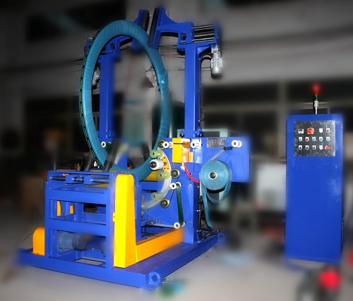
The coil transfer car is engineered as a self-propelled, rail-guided material handling unit designed to stabilize eye-horizontal coils along fixed plant coordinates. Structural steel chassis weldments support a reinforced central cradle engineered to distribute concentrated dead loads across heavy-duty flanged steel track wheels.
Lateral stability is mechanically enforced by adjustable retaining arms that secure the slit coil against axial tipping throughout the transfer stroke. Motorized rail travel along ground-level tracks provides guided positioning between the slitting line exit gate and automated downstream packaging machinery. Exact travel track lengths, lifting stroke dimensions, and saddle radii are customized and frozen against final plant layout drawings prior to manufacturing.
Coil car selection data
The following engineering dataset outlines standard baseline sizing for an illustrative slit-coil handling project.
| Item | Example project values (confirm on order) |
|---|---|
| Max coil weight (example) | 5 t |
| Coil OD (example) | 1,250 mm |
| Coil width (example) | 500 mm |
| Track length (example) | 12 m |
| Travel speed (example) | 12 m/min |
| SWL sizing factor | ≥ 1.25 × max coil |
| Drive | Geared motor + inverter |
Final safe working load (SWL), transit speeds, wheel diameters, and rail profiles (e.g., square bar or standard crane rail) are formally locked following engineering review of your full coil dimension schedule and physical layout drawing.
Beyond custom project parameters, standard heavy-duty coil transfer car platforms offer engineered capacities up to 20 t maximum load, standard 380 V 60 Hz electrical systems, and orbital rail transfer with optional 360° turning table configurations [manufacturer rating], subject to formal quotation and technical review.
Worked example: a 5 t slit coil on a 12 m track
Consider an illustrative slit coil handling application operating under the following design criteria:
- Maximum coil mass: 5 t
- Coil outer diameter (OD): 1,250 mm
- Coil package width: 500 mm
- Track transit length: 12 m (between slitting exit buffer and packaging line infeed)
- Target nominal travel speed: 12 m/min
Load (SWL). To accommodate dynamic impacts, floor irregularities, and localized deceleration forces, the machine frame must incorporate a structural sizing margin of at least 1.25× maximum coil mass:
- Required minimum SWL: 5 t × 1.25 = 6.25 t
- The chassis, wheel bearings, and lift mechanism are therefore assigned to a ≥ 6.25 t structural capacity class.
Trip time.
- Steady-State Transit: Traveling 12 m at a sustained rate of 12 m/min requires approximately 60 s (12 m ÷ 12 m/min × 60 ≈ 60 s) of linear motion in one direction.
- Soft start/stop and lift: Soft start/stop ramps and any lift stroke at pickup and drop-off come on top of the 60 s transit, so the practical one-way cycle is confirmed against the line layout.
- Return and Fleet Layout: An unloaded return run requires roughly 60 s of transit. If a single car serves a fast packaging cycle, round-trip deadheading can constrain system takt time. A dual-car system, or dual buffer pockets at the infeed, cuts this wait when both stations are busy.
Engineering Takeaway: Always submit the maximum coil dimensions, weights, and precise station-to-station distances before drive motor power and SWL ratings are finalized.
Selection checklist: what to send us
To enable our mechanical engineering team to configure the optimal transfer car and track configuration, please provide the following specification data:
- Coil Dimensional Envelope: Maximum and minimum coil outer diameter (OD), inner diameter (ID), strip width range, and maximum individual coil weight.
- Floor Track Geometry: Total track transit length, number of discrete positioning stops, and track rail mounting conditions (surface-mounted vs. embedded flush-floor track).
- Fleet Configuration: Single transfer shuttle versus dual-car parallel shuttle arrangement based on target cycle takt.
- Elevation and Stroke Profiles: Required vertical lift stroke, pick-up centerline height at the turnstile/recoiler, and handover discharge height at downstream stations.
- Destination market for the safety file.
Safety and EN 415-10
For machinery deployed within CE jurisdictions, packaging line handling machinery must comply with the requirements of EN 415-10 (Safety of packaging machines – Part 10: General requirements) evaluated under an overarching ISO 12100:2010 risk assessment protocol.
Primary mechanical and operational hazards include:
- Crushing and Shearing Zones: Pinch points created by mechanical retaining arms during clamping sequences and vertical saddle motion.
- Track Runover Hazards: Risk of personnel contact along the linear travel rails during automated traverse.
- Station End-Stop Overrun: Collision hazards at terminal buffer boundaries.
Guarding is set per project: fence or light curtain where the layout is open, and interlocks and E-stops written into the project risk file. Keep the track clear while the car moves.
Engineering FAQ
Q: Why choose a track-bound coil transfer car over a C-hook crane system? A: A track-bound transfer car maintains a dedicated, low-profile, and strictly repeatable motion profile. It operates independently of facility overhead crane traffic, eliminates swinging load hazards, and integrates directly with upstream PLC networks to achieve fully automatic station handover. For high-capacity master coil staging, heavy-duty rail transfer cars can be scaled up to 20 t maximum load [manufacturer rating].
Q: When is a dual-car layout necessary compared to a single shuttle car? A: A single car suits a straightforward, single-stream path. When a slitting line feeds two packaging stations at once, or wait time at the wrapper must stay low, dual cars on independent tracks keep the line flowing. For specialized multidirectional layouts, transfer platforms can also be engineered with orbital 360° turning capability [manufacturer rating].
Q: Does the coil car perform any packaging or strapping functions? A: No. The coil car functions exclusively as a high-precision transfer, lifting, and positioning module. Dedicated operations such as orbital stretch wrapping, circumferential strapping, downending, or palletizing take place at specialized downstream stations.
Q: Which harmonized safety standards govern the coil car under CE machinery directives? A: The integration of coil transfer machinery on packaging lines is referenced under EN 415-10, with mechanical hazard identification, pinch point containment, and safety control architecture verified through ISO 12100:2010 design safety assessments.
Next step
- Send max coil weight and the floor distances to info@fhopepack.com.
- We map it to car SWL, track geometry, and single- versus dual-car layout configurations.
- We reply within 24 hours with a conceptual layout sketch, trip-time calculation, and formal equipment estimate.
Related reading
- Next-Generation Steel Coil Packaging Solutions
- Inside Customer Workshop: Automatic Steel Coil Upender Wrapping
- Automated Slit Coil Packing Line for Service Center
- Trolley Car for Steel Coil with Track
- Slit Coil Upending & Wrapping Line
- Steel coil wrapping machine (product)
Sources
- Machine features from our coil car for slit-coil packaging lines (central cradle, retaining arms)
- Line practice: one vs two cars between recoiler and packing stations
- Worked example: illustrative coil and track figures
- Standards: EN 415-10; ISO 12100:2010
- Steel Coil Transfer Car | Copper Coil Car
Last reviewed: 2026-10-18