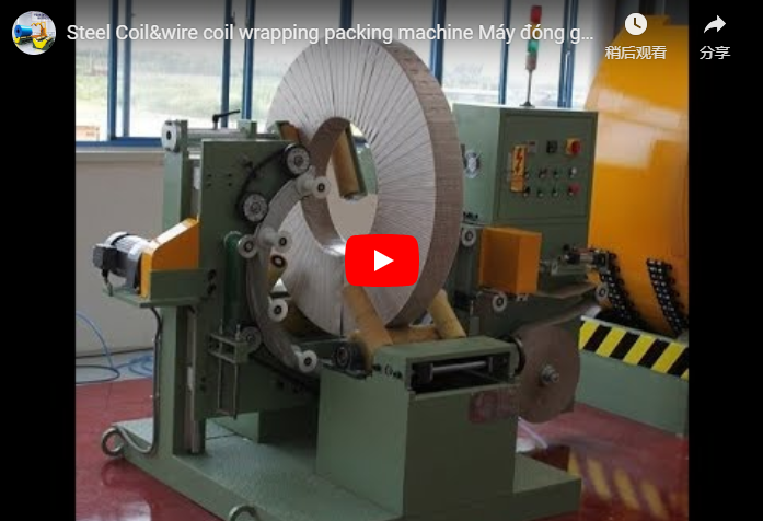
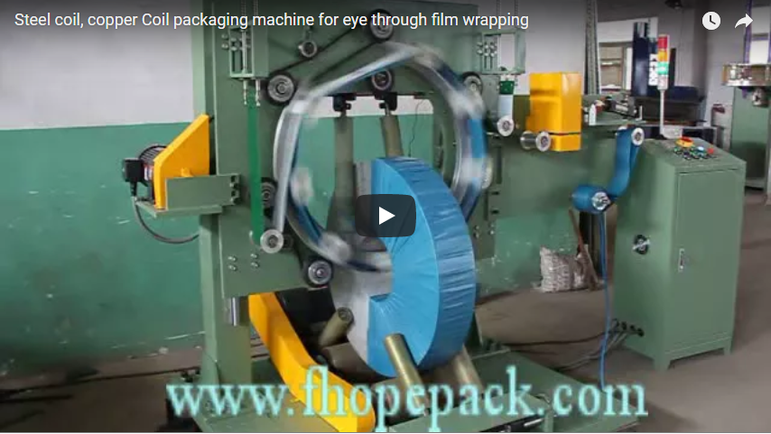
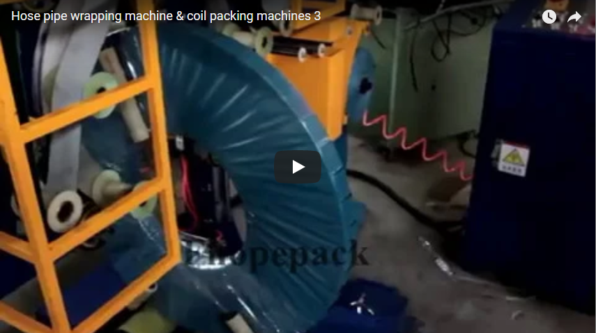
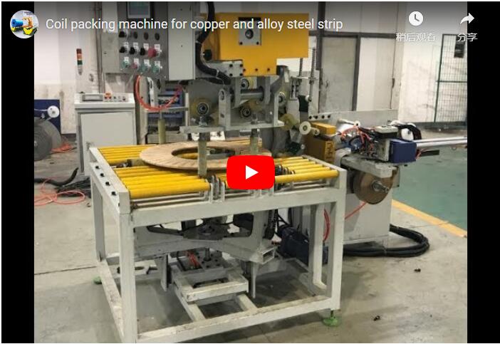
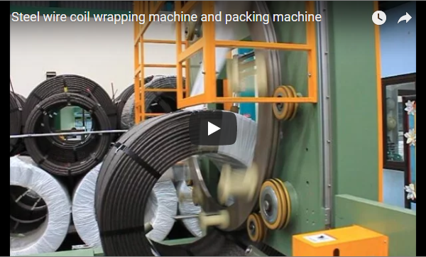
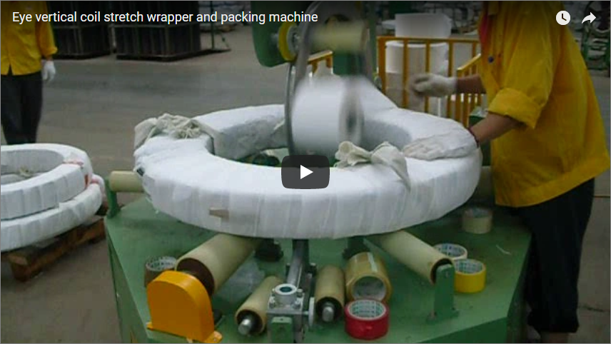
A unified eye-through coil packing machine wraps wire coils, slit steel strips, and plastic pipe coils by positioning the coil upright on motorized support rollers while an orbital shuttle ring passes wrapping media continuously through the coil’s center eye. This radial-through-eye wrapping method delivers 360° sealed encapsulation against atmospheric corrosion, edge impact, and layer shifting during transit. Operating parameters—including ring rotation speed, roller drive ratios, tension levels, and total wrap counts—are tailored to specific coil dimensions and material characteristics.
Overview
The eye-through orbital wrapping system automates protective packaging for open-eye cylindrical loads across metallurgical and polymer manufacturing operations. By synchronizing the rotation of the workpiece on twin polyurethane-coated drive rollers with the continuous rotation of an orbital ring through the inner aperture, the machine applies a uniform helical layer of stretch film, woven plastic tape, or VCI paper.
This mechanical layout eliminates the labor hazards and physical fatigue of manual eye-through threading while establishing continuous structural containment across the entire annular core.
How the Coil Packing Machine Works
The eye-through orbital packaging process secures loose outer wraps and shields internal and external circumferences through coordinated dual-axis kinematics:
- Upright Coil Placement: The coil is loaded in a vertical (eye-horizontal) orientation onto dual floor-level support rollers. These rollers feature heavy-duty polyurethane (PU) wear sleeves to prevent scuffing on sensitive metal or polymer surfaces while maintaining high frictional traction without slippage.
- Ring Alignment and Penetration: The closed orbital shuttle ring—mounted on an adjustable structural frame—aligns its operational trajectory through the central core (eye) of the coil.
- Dual-Axis Synchronized Wrapping: As the rotating ring carries the material shuttle through the coil inner diameter, the base drive rollers rotate the coil around its horizontal centerline. The coordinated velocity ratio between ring rotation (r/min) and roller turning speed (m/min) determines the precise helical pitch and surface overlap.
- Tensioned Film Application: Wrapping material feeds through a mechanical friction brake or pneumatic tensioning mast, generating steady radial containment force without crushing hollow cores or tearing over metallic edges.
- Cut and Discharge Cycle: Upon reaching the pre-set rotational wrap count, motion halts automatically for film cutting and trailing-edge clamping, allowing the encapsulated coil to exit via hoist, crane, or automated roller conveyor.
Ring rotation (orbit) and coil rotation (spin) run on separate drives. The ring carries the film shuttle through the eye; the polyurethane rollers spin the coil on its own axis. The velocity ratio between the two sets the helical pitch and the overlap.
Wire, Steel, and Pipe Coils: Protection Matrix
A single orbital wrapping station accommodates distinct industrial coils by adjusting packaging tension, carrier media, and overlap percentages to address material-specific failure modes.
Packaging consumables must meet standardized dimensional boundaries: roll core inner diameter ID 50 mm, outer diameter OD 100–450 mm, and material width 100–150 mm. Material selection depends on surface vulnerability—such as LLDPE stretch film, PE film, PVC, crepe paper, HDPE woven tape, or composite VCI barrier paper—rather than simply increasing film thickness to mitigate edge shearing.
| Coil Category | Material Vulnerabilities | Primary Protective Function | Recommended Packaging Media |
|---|---|---|---|
| Wire Coil (Rod, Spring, Cable) | Loose outer wraps, spring-back hazards, surface oxidation | Radial retention to prevent turn unraveling; full environmental barrier | Crepe paper, LLDPE stretch film, or woven HDPE tape |
| Steel Strip Coil (Slit Coils, Cold Rolled) | Shearing damage on corners, moisture condensation, rust | High edge-tear resistance; dynamic vapor corrosion inhibition (VCI) | VCI anti-corrosion film, PE composite barrier paper, heavy woven wrap |
| Plastic Pipe Coil (HDPE, PEX, Corrugated) | UV photo-degradation, particulate entry, ovality collapse | UV barrier shielding; soft-surface binding without crushing annular walls | UV-stabilized LLDPE stretch film, co-extruded white barrier film |
Standardized Model Selection by Coil Weight and Geometry
To ensure operational balance, drive power, and structural clearances, wrapping stations are classified into distinct machine frames:
| Model Series | Target Coil Type | Weight Range | Coil OD Range | Coil Width Range | Motor & Air Supply | Packaging Cycle / Speed |
|---|---|---|---|---|---|---|
| FPS-300 | Light Wire / Narrow Strips | 20–1000 kg | 600–1200 mm | 100–300 mm | 1.5 kW; 380V 50Hz 3Ph; Air: 4–6 bar | Overlap: 10–90% adjustable |
| FPS-400 | Medium Slit Steel Coils | 100–2000 kg | 800–1400 mm | 100–400 mm | 4.0 kW; 380V 50Hz 3Ph; Air: 5–7 kgf/cm² | Overlap: 10–90% adjustable |
| FPS-500 | Intermediate Width Coils | 80–1000 kg | 700–1400 mm | 200–500 mm | 2.0 kW; 380V 50Hz 3Ph | 20–45 s/pcs |
| FPS-800 | Wide Strip Steel Coils | 200–1000 kg | 800–1400 mm | 400–800 mm | 1.5 kW; 380V 50Hz 3Ph; Air: 5–7 kgf/cm² (optional) | Overlap: 10–90% adjustable |
| FPCA-1200 | Heavy Copper & Steel Coils | 100–2500 kg | 800–1400 mm | 20–500 mm | 380V 50Hz 3Ph; Air: 5–8 bar | 40–70 s/pcs; Ring: 8–80 r/min; Roller: 12 m/min |
Setting Wraps for Full Cover
Achieving continuous encapsulation depends on controlling the material pitch across both the coil Outside Diameter (OD) and the axial width. Because linear surface speed is greatest at the OD, film overlap is lowest at the outer perimeter and highest along the inner core ID.
To configure the packaging cycle from an empirical estimate into an exact engineering formula, the minimum required wrap count across the face is governed by:
Advance Pitch per Turn = Material Width × (1 – Overlap Ratio) Wraps for Full Axial Coverage ≈ Coil Width / Advance Pitch Total Outer Ring Cycles = Outer Circumference / Advance Pitch Where:
Outer Circumference = π × ODOverlap Ratiois set between 0.10 and 0.90 (10% to 90%).
Engineering Benchmark Example
For an industrial coil measuring 600 mm ID × 1,000 mm OD × 300 mm Width, utilizing 100 mm wide packaging media with a specified 50% overlap (0.50) on the exterior face:
| Parameter Metric | Calculation Basis | Resultant Value |
|---|---|---|
| Advance Pitch per Turn | 100 mm × (1 – 0.50) | 50 mm |
| Axial Face Passes Required | 300 mm / 50 mm | 6 passes |
| Outer Circumference | π × 1,000 mm | 3,142 mm |
| Wraps for Full OD Circumference | 3,142 mm / 50 mm | 63 ring cycles |
| Inner Circumference | π × 600 mm | 1,885 mm |
| Resultant Inner Advance Pitch | 1,885 mm / 63 cycles | 30 mm |
| Resultant Overlap at Inner Eye | [1 – (30 mm / 100 mm)] × 100% | 70% overlap |
Setting the dual Variable Frequency Drives (VFDs) to execute 63 ring cycles per single coil revolution guarantees a minimum 50% overlap along the outer circumference while automatically providing a reinforced 70% protective barrier through the inner eye.
Controls and Safety Integration
Industrial orbital wrapping machinery contains substantial rotating mass operating at peripheral velocities exceeding 2.5 m/s. Integrated machine safeguards prevent operator contact during operational sequences:
-
Perimeter Mesh Guarding: High-visibility safety enclosure prevents operator access to the rotating ring assembly, guide track wheels, and dispenser carriage.
-
Zero-Speed Infeed Inhibit: System logic restricts crane or hoist loading until zero-motion feedback confirms the ring is locked at home position.
-
Regulatory Harmonization: Structural architecture and safety interlocks align with ISO 12100 for basic risk assessment and EN 415-10 for industrial packaging equipment safety. Compliance documentation and CE markings are validated against specific contract configurations.
Technical Selection Checklist
To determine the frame geometry, roller configuration, and drive ratings for your facility, confirm the following application parameters:
- Coil Dimensional Envelope: Minimum and maximum ID, OD, axial width, and gross piece weight across every coil type (e.g., matching within 20–2500 kg capacity).
- Cross-Sectional Clearance: Verification that
(OD - ID) / 2plus dispenser offset fits inside the orbital ring opening:Ring Clearance Diameter ≥ √((Coil Width)² + (Coil Wall Thickness)²) + Dispenser Offset - Throughput Target: Target capacity expressed in coils per hour or packaging cycle time (e.g., 20–45 s/pcs on FPS-500 or 40–70 s/pcs on FPCA-1200).
- Packaging Substrates: Material type (LLDPE stretch film, reinforced VCI paper, woven PE/HDPE tape), core ID (50 mm), and roll width (100–150 mm).
- Material Handling Interface: Coil placement method (overhead C-hook crane, jib crane with internal tong, or integrated floor conveyor).
- Line Footprint & Utilities: Floor space, crane hook clearances, pneumatic supply (4–8 bar), and 380V 50Hz 3-phase electrical supply.
Engineering FAQ
Can one machine wrap wire, steel strip, and plastic pipe coils interchangeably?
Yes, provided that your smallest inside diameter provides sufficient passage for the orbital dispenser carriage, and your heaviest coil does not exceed the mechanical weight rating of the drive rollers (e.g., up to 2000 kg on FPS-400 or 2500 kg on FPCA-1200).
Why is through-the-eye wrapping superior to external sleeve wrapping?
Eye-through orbital wrapping creates a unified, hoop-stress package. It physically anchors loose outer and inner tail ends to the core structure, preventing axial layer shifting and telescoping during intermodal shipping.
How does the control system maintain uniform overlap?
Variable Frequency Drives (VFDs) regulate both the orbital ring motor and the base roller drive motor. By governing the drive speed ratio through an industrial PLC, the surface advance pitch remains constant regardless of line speed fluctuations.
How are light or flexible coils prevented from shifting during wrapping?
For light wire coils or flexible plastic pipe coils prone to jumping under film tension, top and side-stabilizing rollers (pneumatically actuated with adjustable holding force) secure the coil firmly down against the drive rollers.
Next Steps
We engineer coil packaging stations to your exact factory dimensions through a standard three-stage implementation:
- Parameter Review: Submit your coil size matrix (ID/OD/Width/Weight) and desired production capacity to info@fhopepack.com. Our engineering group returns an initial system proposal and clearance drawing within 24 to 48 hours.
- Kinematic & Layout Approval: Review the calculated wrap cycle times, film yield rates, and equipment integration layout.
- Site & Safety Verification: Confirm floor loading capacities, electrical configurations, and factory infeed methods before manufacturing release.
Related Solutions
- Automatic Coil Packing Line — Integrated industrial coil wrapping, transport, and stacking automation.
- Steel & Copper Coil Eye-Through Wrapping System — High-speed orbital eye-through wrapping machines for metals.
- Heavy-Duty Steel Coil Strapping Machinery — Automated radial and circumferential strapping systems for slit coils.
Last reviewed: 2026-11-05