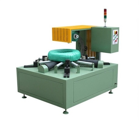
Coil Packing Line Layout Planning: A Practical Guide
How to plan the layout of an automatic coil packing line — map normal and exception flow, size the buffers, keep material and data flow together, reserve access for people and materials, and plan utilities on one drawing.

How to Plan the Layout of an Automatic Coil Packing Line
How to Plan the Layout of an Automatic Coil Packing Line
A good packing-line layout does not start with placing machines on a floor plan. It starts with the material flow, the handoff points, and the recovery route. If the layout only shows normal operation, it will look clean on paper and fail during the first blocked coil.
This guide helps factory planners, engineers, and project teams turn a process sequence into a usable layout for an automatic coil packing line.
| Layout element | What it must show |
|---|---|
| Normal flow | Required stations and their sequence |
| Exception flow | Where a blocked or rejected coil waits and how it returns |
| Buffers | Positions, capacity, and ownership |
| Data handoffs | Where identity, weight, recipe, label, and release decisions happen |
| Access | Operator and maintenance routes, including material replenishment |
| Utilities | Power, compressed air, hydraulics, data network, foundation, and drainage |
Start with the Required Flow
List the stations in sequence: receiving or transfer, buffering, orientation change if needed, identification, wrapping, strapping, weighing, labeling, inspection, stacking, and discharge. Mark which stations are required and which are optional for the current product family.
The layout must show the normal route first, then the exception route.
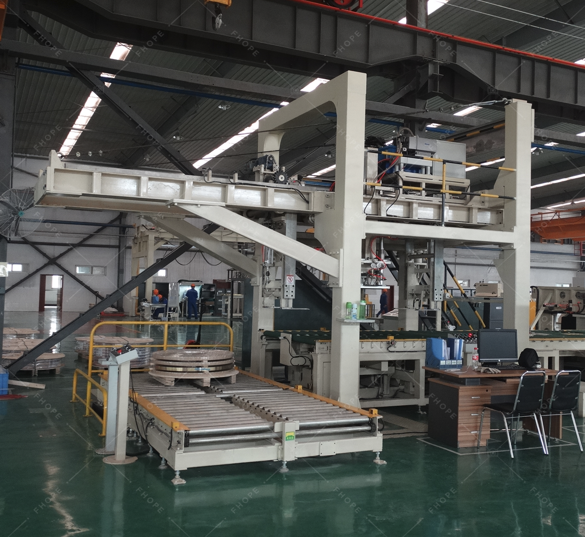
The image shows a stainless steel coil packing machine line installation. It illustrates why the layout is built around the connected equipment sequence, not around one machine placed on a drawing.
Use the Actual Coil Population
Place dimensions and weights on the layout for the representative and extreme coils. Confirm that the handling path, roller widths, station openings, and stacking area match the real population. A layout that fits only the average coil is not complete.
Also show the required orientation of the coil at each station. A change from eye-vertical to eye-horizontal, or the reverse, creates a handling and control boundary that must be designed deliberately.

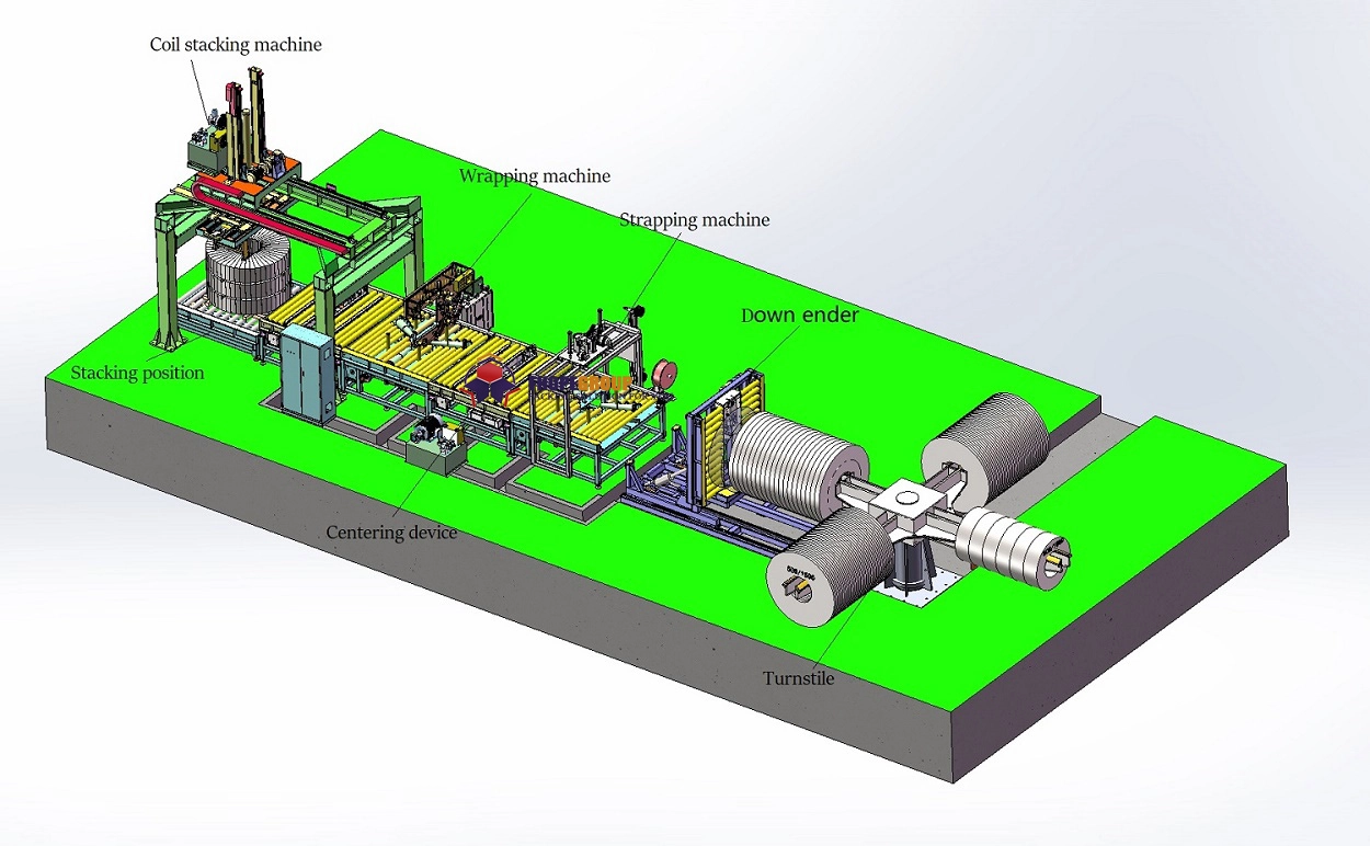
The image shows a steel coil packing line system layout. The population data, station sequence, and buffer positions need to be readable from this kind of layout before equipment is fixed in place.
Keep Material and Data Flow Together
Physical flow and information flow should be drawn on the same diagram. Show where the coil identity is read, where weight is captured, where the packaging recipe is selected, where the label is verified, and where the release decision is made.
If a coil can move physically before its data is correct, the layout must show the buffer or correction point for that exception.
Design Buffers, Not Just Stations
Show the number of coil positions between stations, especially between production or slitting output and the wrapping station. The buffer must cover normal variation and short interruptions without creating a different safety or handling risk.
State the ownership and capacity of each buffer. "Some space on the floor" is not a buffer.
Reserve Access for People and Material
Operators and maintenance personnel need safe access for loading film or strapping, confirming a first article, inspecting a package, and recovering a fault. Draw those access routes separately from the automated movement path.
Material replenishment should not require entering a running guarded area. The layout should show the replenishment position and the safe procedure required to reach it.
Plan Utilities and Installation
Mark power, compressed air, hydraulics, data network, foundation, and drainage positions. Include door width, column clearance, ceiling or crane height, floor loading, and the route used to bring equipment into the building.
An installation conflict discovered after procurement is as serious as a process conflict. When you plan the equipment positions for an automatic coil packing line, utilities and installation access belong on the same drawing.

The image shows a coil packing line layout drawing. This is the level of detail the layout needs: station positions, material paths, and support zones should be visible before the design is frozen.
Include the Exception and Recovery Lane
For each exception, show where a blocked or rejected coil can wait, who may move it, and how it returns to normal flow. The lane must preserve safety and data integrity. A layout without a recovery lane will invent one under pressure.

The image shows a design review scene where normal path, abnormal path, machines, and support zones are considered in one view. That is the right way to plan the layout: the exception route is not a later correction, it is part of the same drawing.
A Practical Next Step
Draw the normal flow, exception flow, buffer positions, data handoffs, access routes, and utility positions on one plan. Walk the plan with operations, quality, maintenance, automation, and safety before freezing the equipment positions.
Watch a stainless steel coil strapping, wrapping and stacking line in operation:

Visual Details
Click to enlarge
Click to enlarge
Click to enlarge
Click to enlarge
Watch How It Works
Discover how our automated packaging solutions optimize your production line efficiency. This video demonstrates the seamless operation designed for maximum protection.
Trusted by Steel Mills & Industry Leaders
Global manufacturers rely on FHOPE heavy duty packaging equipment


Ready to optimize your packaging line?
Get a custom quote with ROI analysis. Our engineers respond within 24 hours.
- Free layout design
- Global installation support
- 2-year warranty included
Your information is secure and will never be shared.
Related Machines
Steel Coil Packaging line
View Details →
Vertical coil packaging line
View Details →
Hose Coil Packaging line
View Details →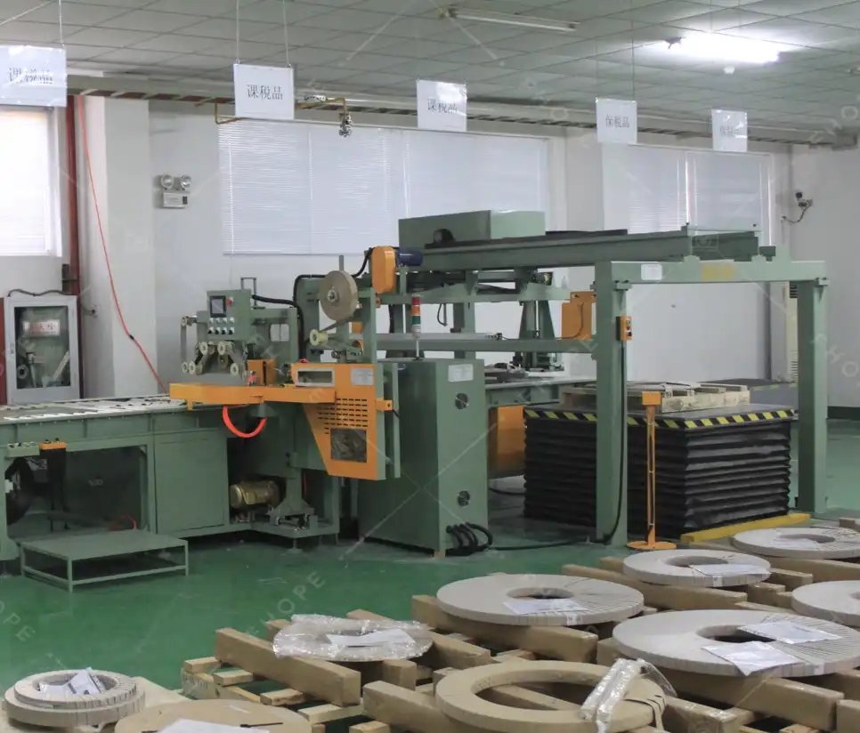
Copper Coil Packaging line
View Details →
Wire Coil Packaging line
View Details →
Panel Packaging line
View Details →
Pipe Bagging Machine
View Details →
Aluminum profile packing line
View Details →
FHOPE Automatic pipe tube bundling&strapping line
View Details →
Automatic pipe tube bundling & strapping line
View Details →
Automatic steel tube strapping machine
View Details →
FHOPE Automatic steel tube packing machine
View Details →
Automatic plastic Pipe strapping packing line
View Details →
Automatic PPR/PVC Pipe bagging line
View Details →
Platsic pipe bag packing machine
View Details →
Tyre Packing Machine FPT-200
View Details →
Tyre Packing Machine FPT-300
View Details →
Tyre Packing Machine FPT-400
View Details →
Cable Coil Packing Machine-FPCA100
View Details →