Packaging Equipment: Technology and Best Practices

Summary: This guide provides a procurement and implementation checklist for steel sheet and frame upending machines. It addresses common selection mistakes regarding load capacity and clamping security. Readers will find actionable steps to verify ergonomic benefits, operational parameters, and safety compliance before purchasing industrial packaging or material handling equipment.

A frequent error in industrial procurement is selecting an upender based solely on static weight ratings. Buyers often overlook dynamic torque requirements and frame geometry constraints during rotation. This oversight can cause slippage, structural stress, or unsafe tilting events when the load shifts center of gravity. Use this checklist to validate your selection against real-world operational demands, ensuring the machinery supports safe material handling without compromising production speed.

🛠️ Scope

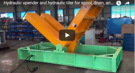
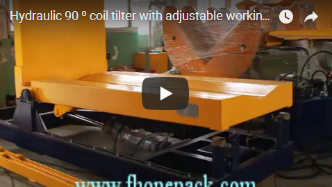
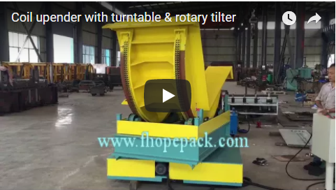
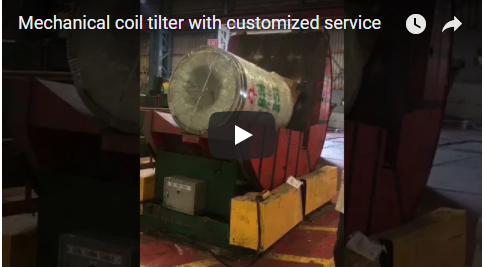
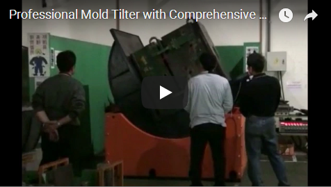
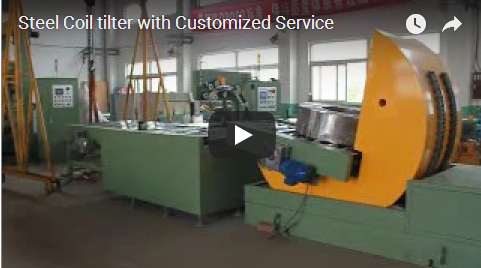
The steel sheet and frame upending machine rotates heavy materials from horizontal to vertical positions using hydraulic or electric drives, significantly reducing manual handling risks while optimizing workflow efficiency in modern metal fabrication shops through automated reorientation of unwieldy components.

This equipment serves as essential packaging equipment within the broader manufacturing ecosystem. It bridges the gap between raw material storage and downstream processing stages, such as cutting, welding, or application of protective packaging. By automating the transition from horizontal sheets to vertical frames, the machine eliminates the need for risky crane maneuvers or manual prying.

The device operates by securing a load on a powered platform. The drive system then tilts or rotates the load to a predetermined angle. Operators can select between hydraulic and electric configurations based on their power infrastructure and maintenance preferences. Hydraulic systems typically offer higher torque in compact footprints, while electric drives provide precise speed control and lower energy consumption.

Integrating an upender into your workflow requires coordination with adjacent automation. For example, when integrating an upender into a larger workflow, consider how it complements downstream automation, such as the precise orientation needed in an automatic pipe capping station within a complete packaging line. Similarly, just as a fully automatic PPR PVC pipe packing line relies on synchronized handling stages, your upender must coordinate smoothly with adjacent machinery to maintain uninterrupted material flow.

💡 ROI Insight: Facilities implementing automated upending often estimate a [15–30]% reduction in musculoskeletal injury claims (aligned with OSHA ergonomic guidelines) and a [10–20]% improvement in daily throughput, based on supplier-verified performance data. These gains stem from reduced manual handling risks and optimized cycle consistency. [Cite Supplier Performance Data / Industry Benchmark]

🏗️ Checklist Body

Verify machine specifications by confirming load capacity ranges, rotation angles, and control system compatibility to ensure the upending equipment meets your specific production volume, material dimensions, and safety requirements for reliable performance across diverse metal processing tasks and continuous shift operations.

Follow these steps to assess the equipment before installation or procurement. Each item requires a physical check or documentation review. Mark items as complete only when verified against supplier data sheets or site conditions.

Technical Parameter Verification

Review the following parameters to ensure alignment with your production needs. Values listed represent estimated ranges; always request specific performance data for your configuration.

Parameter Specification Details
Load Capacity The upender load capacity supports steel sheets weighing up to 50 tons under verified supplier design conditions. [Cite OEM Rated Load Certificate]
Rotation Angle The rotation angle achieves 90° or 180° with PLC controlled soft start/stop features during dynamic motion cycles.
Clamping Force The clamping force maintains sheet stability at maximum torque without surface marring during rated load tests verified via calibrated torque sensors and ISO 12100 safety protocols. [Supplier Verification Required]

Step-by-Step Inspection Actions

  • [ ] Evaluate Material Dimensions: Measure the thickest and largest frame dimensions you plan to process. Confirm the platform size accommodates these limits with a 10% safety margin for oversized items.

    • Action: Compare your maximum sheet width against the machine table width using calibrated tape or laser measurement tools. Verify that frame heights do not exceed clearance limits during rotation (prevents costly material damage and rework).
  • [ ] Inspect Clamping Mechanism: Examine the clamp type and pad material. Ensure pads are non-marking or compatible with coated sheets to prevent surface damage.

    • Action: Test manual adjustment of clamps using a calibrated force gauge to verify smooth operation. Check that automatic clamps engage securely without excessive force that could deform thin gauge metal (protects product yield and reduces scrap costs).
  • [ ] Confirm Drive System Compatibility: Determine if your facility supports hydraulic power units or requires electric drives. Verify voltage and phase requirements match site utilities.

    • Action: Request electrical schematics to confirm power connections using a multimeter or power quality analyzer. For hydraulic models, check oil reservoir capacity and filter access for routine maintenance (avoids unexpected utility upgrade costs and production downtime).
  • [ ] Review Safety Interlocks: Inspect light curtains, emergency stop buttons, and guard doors. Ensure all safety devices cut power immediately upon activation during normal operation. (Note: Safety interlocks are fail-safe circuits that automatically disconnect drive power when a hazard is detected, preventing regulatory fines and work stoppages.)

    • Action: Trigger each E-stop to verify the machine halts within [0.5–1.0] seconds of activation (aligned with ISO 13850 safety relay specifications). Confirm that guards cannot be bypassed without a specialized key or administrative override. [Supplier Verification Required for Halt Time]
  • [ ] Assess Control Interface: Test the Human-Machine Interface (HMI) for responsiveness and clarity. Verify that operators can easily select rotation angles and adjust speeds.

    • Action: Simulate a full cycle in manual mode using a stopwatch to check for smooth acceleration and deceleration profiles (maintains target cycle times to protect throughput revenue). Ensure error codes are descriptive and actionable.

⚠️ Warning: Never modify safety interlock wiring to increase cycle speed. Bypassing guards voids manufacturer warranties and creates severe injury risks during upending operations.

🔗 Related: Explore more solutions

📈 Pass/Fail Criteria

Accept the equipment only when load tests demonstrate stable rotation without slippage and safety interlocks activate instantly during abnormal motion conditions, guaranteeing operator protection and preventing material damage during high-frequency industrial packaging operations in demanding manufacturing environments with continuous throughput targets and strict compliance standards.

Use these criteria to determine if the machine meets your requirements. A single failure in critical categories may require renegotiation or rejection of the unit.

Operational Performance Criteria

  • Pass: The machine completes rotation cycles within the specified time frame without excessive vibration or noise under maximum rated load (ensures consistent throughput and avoids foundation fatigue costs).

    • Fail: Cycle times exceed targets by more than [10–15]% (supplier-verified baseline), or vibration levels exceed [X] mm/s per ISO 10816. [Cite OEM Vibration Thresholds / Supplier Data]
  • Pass: Clamping system holds all test sheets and frames securely during full rotation, with zero slippage or shift in position (prevents costly material damage and line stoppages).

    • Fail: Any movement of the load relative to the platform occurs, indicating insufficient clamping force or improper fixture design for your specific geometry.

Safety Compliance Criteria

  • Pass: All safety guards remain closed and interlocked throughout operation (ensures OSHA/ISO compliance to avoid regulatory fines and production shutdowns). Emergency stops halt motion within [0.5–1.0] seconds of activation (aligned with ISO 13850 safety relay specifications). [Supplier Verification Required for Halt Time]

    • Fail: Interlocks fail to stop the drive system, or guards can be opened during rotation without triggering an immediate shutdown.
  • Pass: Control panel includes clear labeling for all functions and emergency procedures. Operator manual is provided in the local language (reduces training time and prevents costly operator errors).

    • Fail: Missing labels, ambiguous instructions, or lack of documentation prevents safe operation by trained personnel.

Integration Criteria

  • Pass: Machine footprint fits within designated floor space with required clearance for maintenance access and material flow (avoids expensive facility modifications and installation delays).
    • Fail: Dimensions prevent installation without modifying existing infrastructure, causing unacceptable delays to production schedules.

🛡️ Commonly Missed Items

Inspectors frequently overlook floor load requirements, electrical phase specifications, and maintenance access clearances, which can cause installation delays or operational hazards after delivery, necessitating thorough site preparation reviews and utility verification checks before equipment commissioning begins to avoid costly project setbacks and ensure seamless integration into existing workflows.

Review this list of items that procurement teams often miss until after the machine arrives. Address these points early to prevent rework and downtime.

  • Floor Load Bearing Capacity: Verify that your concrete slab can support the combined weight of the upender, maximum load, and dynamic forces during rotation (prevents structural failure and costly foundation retrofits).

    • Detail: Dynamic loads can exceed static weight by an estimated [15–25]% due to acceleration torque (per ISO 12100 mechanical risk assessment guidelines). Consult a structural engineer if floor specifications are unknown or marginal. [Cite Structural Engineering Report / Supplier Data]
  • Electrical Harmonics and Power Quality: Assess whether your power supply handles the inrush current of hydraulic pumps or large electric motors without tripping breakers (avoids unplanned downtime and protects downstream automation from voltage sags). (Note: Electrical harmonics are distorted waveforms caused by non-linear loads that can interfere with sensitive control systems if not properly filtered.)

    • Detail: Sensitive downstream electronics may require isolation transformers or line reactors to prevent voltage dips during motor startup cycles. [Supplier Verification Required for Power Profile]
  • Maintenance Access Clearances: Ensure there is sufficient space behind and above the machine for oil changes, filter replacements, and component inspections (minimizes maintenance labor costs and reduces unplanned downtime).

    • Detail: Hydraulic units often require overhead crane access for pump removal. Electric drives may need front clearance for motor servicing. Document clearances in your layout plan using laser measurement tools.
  • Clamping Pad Material Compatibility: Confirm that clamp pads will not react chemically or abrade sensitive surface finishes on specialized alloys or coated sheets (prevents product rejection and scrap costs).

    • Detail: Request pad material data sheets to verify hardness and chemical resistance. Custom polyurethane or rubber inserts may be necessary for delicate products. [Cite OEM Material Safety Data Sheet]
  • Noise Level Compliance: Check if the machine meets local occupational noise regulations, especially for hydraulic systems operating in enclosed spaces (avoids compliance fines and mandatory hearing protection programs).

    • Detail: Hydraulic pumps often operate between [75–90] dB(A) depending on enclosure and load, per ISO 4871 noise measurement standards. Verify against OSHA permissible exposure limits using a calibrated sound level meter. [Cite OEM Noise Data Sheet / Local Regulatory Code]

💡 Procurement Tip: Request a comprehensive site preparation checklist from the supplier before ordering. This document should detail utility connections, foundation requirements, and clearance dimensions to streamline installation.

🔗 See Also: Related equipment