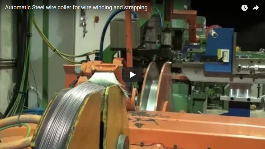
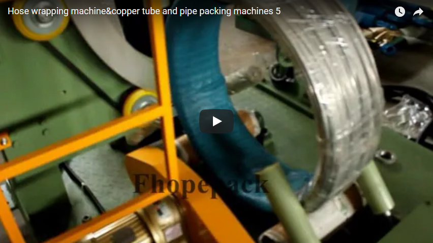
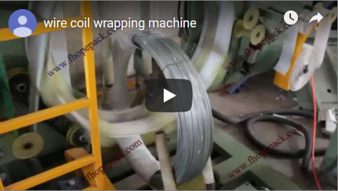
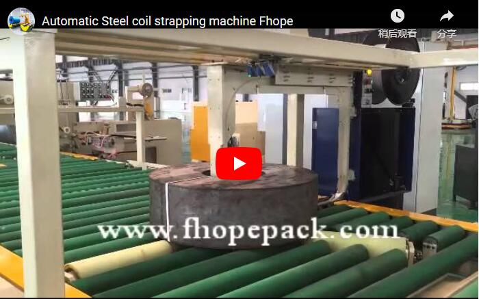
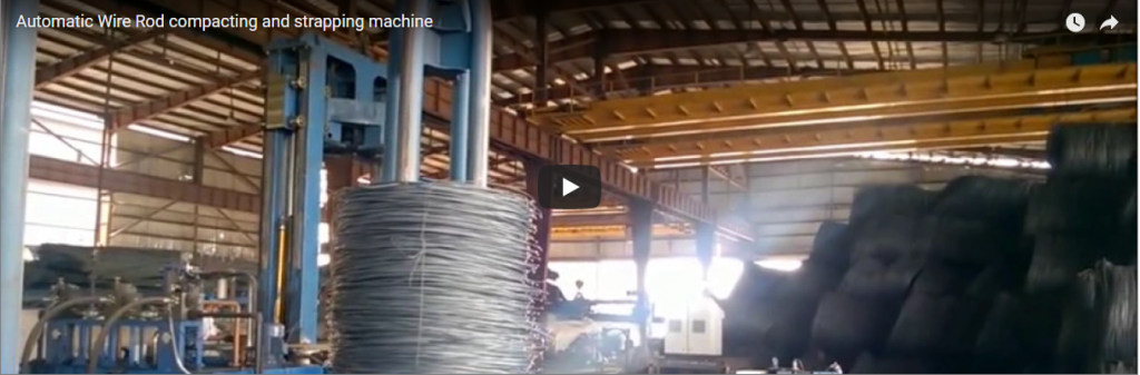
Executive summary In high-capacity steel wire manufacturing plants, decentralizing the finishing process into multiple parallel strapping lines provides higher operational resilience and lower logistics friction than relying on a single centralized system. Steel wire coils travel along dedicated live roller conveyors through automated strapping stations that compress and radially strap each coil before advancing it to discharge staging. Because modern wire drawing mills operate clusters of high-speed drawing machines, allocating one automated strapping line to serve each production group eliminates plant-wide bottlenecks and maintains continuous uptime.
Table of Contents
- How the Lines Run: Layout and Station Sequence
- Why many short lines
- How many lines
- What we set per plant
- Selection checklist
- Safety
- Engineering FAQ
- Next step
- Related reading
- Sources
How the Lines Run: Layout and Station Sequence
A parallel plant layout distributes heavy wire coils across compact, dedicated handling lanes running adjacent to specific drawing blocks. Each automated line executes a four-stage packaging sequence designed to eliminate manual intervention and protect wire surface integrity:
| Process Stage | Equipment & Motion Sequence | Technical Specifications |
|---|---|---|
| 1. Infeed & Buffer | Wire coils are transferred directly from drawing machine payoff carousels onto the line infeed. | Buffers intermittent mill output; supports coil weights from 30 kg to 6,500 kg+ [manufacturer rating]. |
| 2. Powered Conveying | Motorized live roller conveyors transport coils axially into the strapping envelope. | Contact surfaces feature high-durability polyurethane (PU) coating to prevent scratching on galvanized and bright wire [manufacturer rating]. |
| 3. Automated Strapping | Indexing strap chutes pass strap through the coil eye (circumferential/radial banding) under tension. | Individual strapping action completes in ≤35 s/cycle [manufacturer rating]; Siemens S7 PLC controls indexing and multi-strap sequences. |
| 4. Outfeed & Staging | Strapped coils advance to discharge conveyors for automated labeling, weighing, or forklift collection. | Inline integration with high-precision load cells (1/3000 resolution) and automated thermal transfer tag printers [manufacturer rating]. |
Why many short lines
- Short routes. Each line sits directly beside its assigned group of wire drawing machines, minimizing crane transport, internal forklift travel, and floor congestion.
- No single choke point. Because lines operate independently, maintenance, strap coil reloading, or mechanical downtime on one strapping station does not interrupt the rest of the plant.
- Shared design. All parallel lines share identical mechanical drives, pneumatic actuators, wear components, and strapping head assemblies, drastically reducing spare parts inventory.
- Step-by-step growth. Capital expenditure scales alongside plant expansion; additional modular strapping lines can be installed sequentially as new drawing machines come online.
- High payload handling. Standard modules accommodate industrial wire coils with outer diameters (OD) of 500–1500 mm, inner diameters (ID) of 300/508/610 mm, and axial widths of 20–500 mm [manufacturer rating] (compatible with master coils up to 4,000 kg managed by companion handling systems [manufacturer rating]).
How many lines
The total number of packaging lines required is determined by matching the collective throughput of the wire drawing facility against the operational cycle rate of an individual strapping line.
Worked example (illustrative).
| Item | Value |
|---|---|
| Plant output (illustrative) | 600 coils per hour |
| One strapping line (illustrative) | 80 coils per hour |
| Lines needed, 600 ÷ 80 | 7.5, so 8 lines |
| Coils per line at 8 lines, 600 ÷ 8 | 75 coils per hour |
| Coil weight (illustrative) | 1,000 kg |
| Tonnes per line, 75 × 1,000 kg | 75 t per hour |
Engineering note on cycle rates: While a single automated strapping head executes a single strapping band cycle in ≤35 seconds [manufacturer rating], full-line operational throughput typically ranges from 20 to 40 coils per hour per line depending on the number of straps applied per coil (e.g., 2, 3, or 4 radial bands), coil rotation time, and upstream feeding automation [manufacturer rating]. The illustrative 80 coils/hour rate above reflects dedicated single-strap configurations or dual-head tandem operations.
What we set per plant
Every line is tailored to plant layout boundaries, metallurgical surface requirements, and logistical handling methods:
| Setting | Depends on | Factory Configuration Range |
|---|---|---|
| Straps per coil | Coil weight, handling dynamics, and export transport | 2, 3, or 4 radial straps through the coil eye; programmed via 12–15″ touchscreen HMI. |
| Strap material | Wire tensile strength and transport shock loads | Heavy-duty PET strap (friction-weld joint efficiency ≈75%–80%) or high-tensile steel strap (notch or sealless joint). |
| Conveyor type | Coil OD, ID, face width, and floor layout | Polyurethane (PU)-lined steel rollers, V-shaped roller beds for horizontal eye coils, or flat slat conveyors. |
| Line count | Total mill tonnage and drawing cell arrangement | Scaled based on plant output and drawing machine clustering to optimize floor pathways. |
Selection checklist
Ensure the following operational parameters are specified before finalizing line engineering:
- Coil physical dimensions: Minimum and maximum Outer Diameter (OD), Inner Diameter (ID), and Face Width (mm).
- Coil mass: Net and gross weight range (kg per coil).
- Required straps per coil: 2, 3, or 4 radial bands through the core.
- Peak plant output: Coils per hour and total metric tonnes per shift.
- Machine allocation: Number of drawing machines feeding into each strapping group.
- Floor layout & envelope: Available floor length, ceiling crane clearance, and infeed transfer method.
- Strap specification: Polyester (PET) vs. high-tensile steel strap (strap width and thickness).
- Ambient conditions: Standard plant environment (-10 °C to +45 °C) [manufacturer rating].
Safety
High-tension wire packaging systems incorporate comprehensive risk-reduction measures under international standards:
- Strapping head clearance: Personnel must maintain clear boundaries outside the machine guarding envelope while strapping heads and indexing strap chutes are in motion.
- Live conveyor isolation: Operators must never step onto motorized roller conveyors; walkways and crossovers must be utilized.
- Lockout/Tagout (LOTO): Energy isolation protocols (electrical and pneumatic discharge) must be fully executed before clearing strap track blockages, servicing strapping heads, or reloading strap coils.
- Standard compliance: Designed and built for CE compliance in accordance with ISO 12100:2010 (Safety of machinery — General principles for design — Risk assessment and risk reduction) and EN 415-10:2014 (Safety of packaging machines — General requirements).
Engineering FAQ
Q: Why many short lines instead of one centralized packaging hub? A: Multiple short lines place the packaging station immediately adjacent to drawing machine cells. This eliminates long-distance coil transport, prevents a single machine stoppage from halting the entire mill, and allows modular expansion as plant capacity grows.
Q: How many strapping lines does our plant need? A: Divide your peak plant hourly output by the net hourly rating of a single strapping line (rounded up to the next integer). In the worked example above, 600 coils/hour divided by 80 coils/hour requires 8 parallel lines handling 75 coils/hour each.
Q: Should we specify PET or steel strapping? A: High-tensile PET is widely used for wire coils due to its constant retained tension, elastic shock absorption during transit, and lower consumable cost. Steel strap is selected for extremely heavy wire coils, sharp cut-edge products, or extreme high-temperature handling off the annealing line.
Q: Can additional strapping lines be added after commissioning? A: Yes. Because each parallel line operates as an independent automation island sharing standard electrical and mechanical architecture, new lines can be integrated without interrupting active lines.
Q: Do all parallel lines share the same spare parts? A: Yes. All lines utilize unified mechanical drives, PU rollers, strap dispenser carts, strapping head components, and Siemens PLC logic, minimizing warehouse inventory costs.
Q: Which machine safety standards govern this equipment? A: For CE and international markets, the design adheres to ISO 12100:2010 for mechanical risk reduction and EN 415-10:2014 for packaging machine safety.
Next step
Our application engineering team provides custom layout integration and throughput modeling in three direct steps:
- Submit your layout drawing including coil dimensions (OD/ID/Width/Weight), peak plant output, and current factory floor drawings to info@fhopepack.com.
- Receive a formal technical proposal within 48 hours, complete with cycle time calculations, footprint models, and machine datasheets.
- Book an engineering site survey with our specialists to review line clearances, drawing mill integration points, and infeed logistics.
Related reading
- Steel Wire Coil Wrapping, Upending and Stacking Line
- Rebar and Rod Bundle Wire Tying Machine
- Full Wrapping-Through Machine for Small Coils
- Coil packing machine
Sources
- Automatic Wire Coil Packaging Line — FHOPEpack Engineering Specifications
- Big Wire Coil Wrapping Machine FPW-600 Series — System Integration Data
- Plant Throughput Calculation Model — Illustrative capacity planning example
- ISO 12100:2010: Safety of machinery — General principles for design — Risk assessment and risk reduction
- EN 415-10:2014: Safety of packaging machines — Part 10: General requirements
- Official Turnkey Proposal Protocol (Standard 48-Hour Response SLA)
Last reviewed: 2026-10-29
Last updated: 2026-10-29