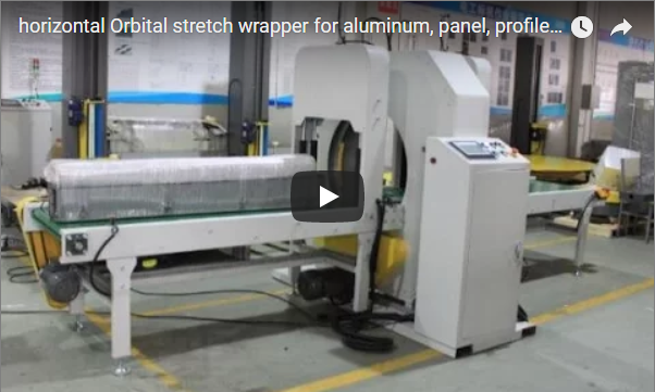
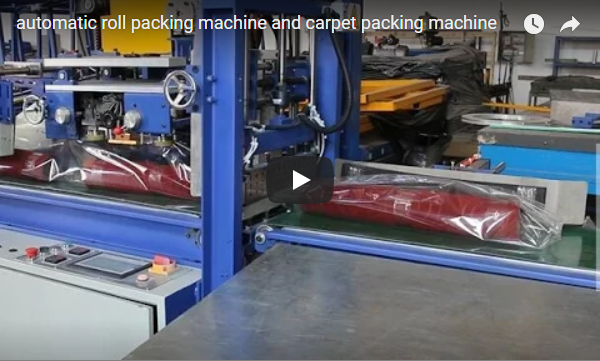
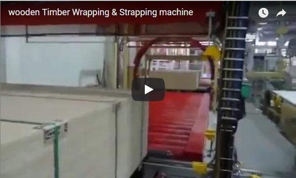
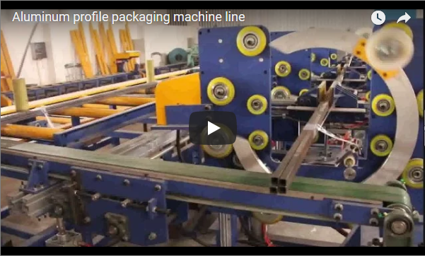
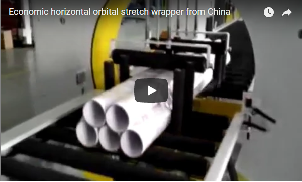
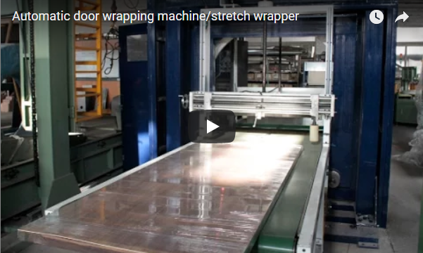
In standard packaging operations, routing unstable packages through an orbital ring poses immediate mechanical hazards. Because the rotating ring must revolve freely around the product pass-line, a physical void separates the infeed and outfeed tables. Short boxes drop into this cavity, soft bundles bow under circumferential tension, and lightweight parcels tilt off line.
A horizontal wrapping machine with a transitional conveyor belt bridges the rotating ring gap to provide uninterrupted bottom support. It prevents short, flexible, or lightweight loads from pitching into the open ring cavity during operation. The linear belt speed and ring rotational velocity synchronize to lock in your exact film overlap ratio.
I have spent over fifteen years commissioning horizontal packaging cells on factory floors. Below, I break down the physical bridging sequence, the synchronization kinematics, the workpiece profiles that demand a belt, and the exact engineering data needed for line integration.
Table of Contents
- What does a horizontal orbital wrapping cell actually do?
- Why must the ring gap be bridged, and how does the belt do it?
- How do conveyor speed and ring speed set the film overlap?
- Which loads actually need a transitional belt?
- How is the cell controlled and safeguarded?
- What should you specify before ordering?
- What else do buyers ask about transitional belts?
- Related Packaging Systems
- Engineering References and Standards
What does a horizontal orbital wrapping cell actually do?
The automated packaging cell consists of three synchronized sub-assemblies: an infeed belt conveyor, a center transitional bridging unit spanning the ring gap, and a driven outfeed conveyor.
The mechanical sequence processes workpieces through four sequential functional stages:
- Infeed Transfer: The incoming package is detected by optical sensors on the infeed bed and conveyed into the center wrapping zone.
- Bridging Transition: The transitional conveyor takes control of the load base, providing continuous planar support as the leading edge enters the orbital envelope.
- Orbital Wrapping: The rotating ring accelerates to the set angular speed. Clear stretch film feeds from the ring-mounted carriage assembly, helical-wrapping the four perimeter faces (top, bottom, and lateral sides) of the advancing package.
- Outfeed and Discharge: As the product clears the rotational boundary, the discharge conveyor receives the wrapped bundle and transports it downstream for palletizing or sorting.
Why must the ring gap be bridged, and how does the belt do it?
The transitional belt conveyor closes the open void between conveyor beds while maintaining dynamic clearance for the rotating film spool. It delivers continuous base contact across the wrapping zone, so cartons do not tip, flexible packages do not sag, and applied film tension does not crush bundle corners.
In conventional horizontal orbital wrappers, an open gap must exist between the infeed and discharge tables. This void allows the rotating ring and its film spool to travel around the workpiece. For long, rigid bars or profiles, simple gap rollers suffice. However, for boxed goods, short bundles, or flexible parcels, this physical interruption poses serious handling risks.
| Stage | Mechanical Action | Engineering Function |
|---|---|---|
| Infeed Transfer | Belt-driven approach | Aligns the package along the machine centerline |
| Gap Transition | Cantilevered transitional belt | Supports the load base across the film-carriage clearance opening |
| Film Encapsulation | Simultaneous rotation and advance | Applies tensioned film around product and conveyor bridge |
| Discharge Transfer | Outfeed belt handoff | Smoothly clears the wrapped package without dragging or tilting |
The transitional belt conveyor eliminates the unsupported void under the ring. It maintains a continuous transport surface throughout the wrapping envelope. Short payloads traverse the open space without pitching downward, jamming against the discharge plate, or sustaining corner deformation from high film tension.
How do conveyor speed and ring speed set the film overlap?
Film overlap depends directly on the kinematic ratio between the linear conveyor speed and the ring rotational velocity. You adjust this ratio to change the spiral pitch per revolution. Running the conveyor slower or running the ring faster increases overlap to provide tighter load containment and weatherproofing.
The containment integrity of the wrapped product depends on the effective film overlap.
The linear advance per revolution (spiral pitch, P) is calculated as:
- Advance per turn:
P = Conveyor Speed (mm/min) ÷ Ring Speed (r/min)
To achieve a designated overlap percentage, the advance pitch must satisfy:
- Advance Pitch per Ring Turn:
P = W_film × (1 − Overlap Ratio)
Kinematic Calculation Example
The following baseline parameters illustrate how this kinematic relationship operates on standard packaging lines:
| Parameter | Value | Engineering Context |
|---|---|---|
Film Roll Width (W_film) |
250 mm | Standard cast LLDPE stretch film roll |
| Target Overlap Ratio | 60% (0.60) | Standard multi-layer protective packaging spec |
Advance Pitch per Ring Turn (P) |
100 mm | Advance Pitch = 250 mm × (1 − 0.60) = 100 mm |
Ring Speed (ω_ring) |
60 r/min | Typical operational ring velocity |
Required Conveyor Speed (V_conv) |
6.0 m/min | Required Speed = 100 mm × 60 r/min = 6,000 mm/min = 6.0 m/min |
Decreasing the conveyor speed or increasing the ring rotation velocity increases the overlap ratio, delivering higher containment force and weatherproofing. Operating at a ring speed of 60 r/min with a conveyor speed of 6.0 m/min aligns directly within the manufacturer rating baseline for our E1000 standard drive platform, which accommodates ring speeds of 10 to 60 r/min and line speeds of 3 to 12 m/min [manufacturer rating].
For installations requiring automated top hold-down mechanisms for unstable parcels, consult our horizontal ring orbital stretch wrapping machine. For continuous building panels and sheet products, refer to our horizontal orbital ring stretch wrapper for sheet metal building materials.
Which loads actually need a transitional belt?
You must select a transitional belt whenever the physical dimensions or structural rigidity of your load cannot bridge an open gap. Short parcels drop forward when their center of gravity overhangs the infeed bed. Light items drift under film tension, and flexible bundles buckle without solid bottom support.
Selecting a wrapper equipped with a transitional belt conveyor is critical when package physical properties cannot sustain an unsupported gap crossing.
| Load Profile | Operating Risk Without Belt | Transitional Belt Advantage |
|---|---|---|
| Short Boxes & Cartons | Center of gravity passes off the infeed edge, causing forward tipping into the ring. | Delivers full-base contact throughout the wrapping cycle. |
| Soft or Flexible Packs | Package corners bow downward under film tension, causing uneven wrapping. | Provides rigid bottom countering against circumferential film pull. |
| Mixed-Length Batches | Short items jam while long items pass, forcing manual line intervention. | Standardizes the transfer path across varying product lengths. |
| Lightweight Items (< 5 kg) | Film application force pulls the parcel off the conveyance centerline. | High-friction belt surface maintains package orientation. |
When ordering, specifying your minimum parcel length (L_min) allows engineering to calculate the correct gap bridge distance and roller transfer transitions.
How is the cell controlled and safeguarded?
High-speed orbital rings generate significant kinetic energy. Safety and automation systems are engineered to prevent operator exposure while sustaining line throughput.
- Fencing and Access Prevention: The rotating assembly is enclosed within a perimeter safety cage. Access panels are monitored by dual-channel safety interlock switches compliant with ISO 14119.
- Drive Synchronization: Ring rotation and conveyor drives are regulated via Variable Frequency Drives (VFD) managed by a central PLC, ensuring constant stretch tension during acceleration and deceleration.
- Safety Circuit Design: Emergency stop actuators and safety circuits are wired to meet ISO 13849-1 Performance Level d (PL d) / Category 3 architecture.
- Standard Compliance: European market deliveries comply with ISO 12100 (safety risk assessment) and EN 415-10 (general safety requirements for packaging machines).
What should you specify before ordering?
Before finalizing machine dimensions and ring size, verify the following mechanical criteria:
- Minimum and Maximum Package Dimensions: Length (
L_min/L_max), Width (W), and Height (H). - Cross-Sectional Ring Diagonal: Ensure ring inner diameter accommodates
√(W² + H²) + clearance. - Weight Range: Minimum and maximum payload weight (g/box up to kg/bundle).
- Required Line Speed: Units per hour and target conveyor advance speed (m/min).
- Film Specifications: Film core diameter (typically 76 mm), roll outer diameter, width (125–300 mm), and gauge (17–35 µm).
- Target Overlap Percentage: Typically 30% to 70% based on moisture and transit requirements.
- Conveyor Interface: Roller pitch, belt material, and integration signals with upstream/downstream lines.
- Facility Power & Pneumatics: Primary voltage (e.g., 380V/480V 3-phase, 50/60 Hz) and clean air supply (0.6 MPa).
What else do buyers ask about transitional belts?
How is the advance pitch per ring turn calculated?
Advance pitch (P) equals linear conveyor speed divided by ring rotational speed (P = V_conveyor ÷ ω_ring). For example, running at 6 m/min (6,000 mm/min) with a ring speed of 60 r/min yields an advance pitch of Advance Pitch = 6,000 mm/min ÷ 60 r/min = 100 mm per ring turn.
Why can a standard roller conveyor not bridge the ring gap?
The film carriage rotates through a 360° vertical circle intersecting the pass-line. A permanent solid roller table would collide with the film dispensing spool. The specialized transitional belt bridges this footprint while preserving dynamic clearance for the revolving film roll.
How do we increase the film overlap percentage on our existing machine?
Adjust the operating ratio on the HMI by reducing the conveyor drive frequency, increasing the ring drive frequency, or utilizing a wider film roll.
Can this system handle parcels of varying lengths consecutively?
Yes. The transitional conveyor operates continuously, allowing both long bundles and cartons as short as the bridging belt contact span to be processed consecutively without manual mechanical changeover.
Does the system support automatic film clamp and cut?
Yes. Pneumatic clamp-and-cut assemblies can be integrated to secure the leading edge and trim the film trailing end automatically at the completion of each wrap cycle.
Conclusion
Select your conveyance setup based on workpiece geometry: long, rigid profiles pass smoothly over basic gap rollers, but short boxes, soft packs, lightweight items under 5 kg, and mixed-length batches require a transitional conveyor belt. For basic product grouping, set overlap to 30%–40%; for moisture resistance and heavy transport stabilization, specify 60%–70% overlap and back-calculate line speed using V_conv = W_film × (1 − Overlap) × ω_ring.
To configure an orbital wrapper tailored to your operational floor space and cycle rates:
- Submit Product Specs: Send your minimum and maximum package dimensions, weights, and hourly output targets to info@fhopepack.com.
- Kinematic & Sizing Plan: Receive a full proposal within 48 hours, including ring diameter calculations, belt speeds, and layout CAD drawings.
- Engineering Consultation: Review conveyor integration points, safety fencing layouts, and site utility requirements with our packaging engineers at FHOPEPACK.
Related Packaging Systems
- Horizontal Orbital Stretch Wrapper – Heavy-duty systems for profiles, bars, and elongated assemblies.
- Video: Horizontal Stretch Wrapper for Light Paper Products – Low-inertia handling for lightweight and compressible bundles.
- Video: Orbital Wrapper for Carton Box Bundles – Multi-pack bundle encapsulation with automated feed indexing.
Engineering References and Standards
- Machine Specifications: FHOPE Packaging Machinery Technical Division
- Kinematic Calculations: Spiral packaging containment geometry (
P = W_film × (1 − Overlap)) - System Demonstration: FHOPE Official YouTube Channel
- Safety & Packaging Standards: ISO 12100:2010 (Risk reduction), EN 415-10:2014 (Packaging machines safety)
Last reviewed by Chief Mechanical Packaging Engineer: 2026-10-04