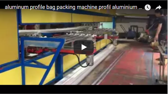
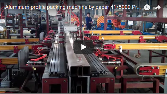
Executive Summary
Mill-finish, anodized, and powder-coated aluminium profiles are highly prone to surface scratching, friction scuffing, and cross-sectional shifting when packaged manually. Uneven manual film tension causes loose bundles that flex during transport, leading to inter-profile friction marks. An automated horizontal orbital stretch wrapping machine eliminates manual packing inconsistencies by conveying the bundle through a high-speed rotating ring. Synchronized pneumatic top-press rolls stabilize the profile stack against rotational film torque, delivering uniform tension, calibrated film overlap, and reliable bundle integrity. This technical guide outlines the machine stations, stabilization kinematics, technical specifications of the E200 series, and precise film consumption formulas.
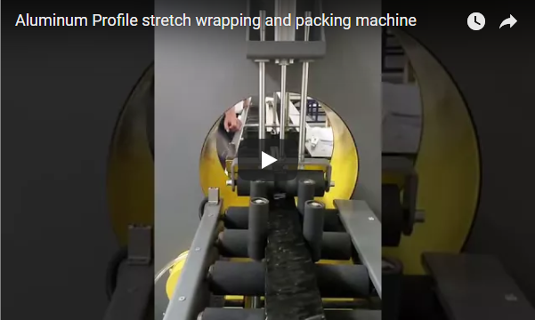
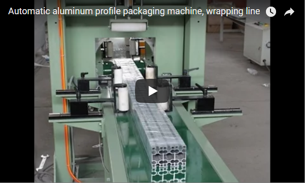
Horizontal orbital wrapping secures elongated extrusion bundles within a continuous through-feed envelope. As the aluminum bundle enters the wrapping center via non-marking flat belt conveyors, dynamic pneumatic hold-down assemblies lock the profiles into a rigid matrix, neutralizing the tangential pulling forces exerted by the rotating film dispenser. Side guide assemblies maintain bundle alignment along the infeed centerline, ensuring uniform film coverage from tip to tail without surface abrasion.
Table of Contents
- Why Aluminium Is Hard to Wrap
- How the Machine Works
- Why the Top Press Matters
- E200 Data
- Film per Bundle Calculation
- Selection Checklist
- Safety Standards and Interlocks
- Engineering FAQ
- Next Step
- Related Reading
- Sources
Why Aluminium Is Hard to Wrap
Mill-finish, polished, and powder-coated aluminium profiles exhibit low surface hardness compared to steel, making them susceptible to scratching, fretting corrosion, and cosmetic scoring. When an extrusion bundle is lifted by crane slings or forklift tines, unsupported profiles flex longitudinally. If the wrap lacks consistent hoop strength, individual pieces slide against each other, grinding residual aluminium swarf into adjacent surfaces and destroying the surface finish.
Manual spiral wrapping cannot maintain constant tension along long extrusions:
- Tension Fluctuations: Operators apply inconsistent tension across long lengths, producing localized slack zones where profiles slip during handling.
- Micro-Fretting Damage: Insufficient circumferential clamping allows internal profiles to oscillate during truck transport, resulting in black friction marks (fretting oxidation).
- Crushed Thin-Wall Sections: Over-tensioning delicate, hollow architectural profiles causes wall buckling, whereas an automated horizontal ring applies controlled radial pre-stretch forces (typically 15 to 45 N) evenly around the cross-section.
How the Machine Works
The automated horizontal wrapping sequence follows an indexed, PLC-synchronized continuous cycle:
- Infeed & Alignment: Profile bundles enter on powered polyurethane-coated rollers. Adjustable vertical guide rollers center the bundle along the ring axis to maintain an equal distance to the rotating film carriage.
- Surface-Safe Conveying: Heavy-duty, non-marking PU flat belt conveyors transfer the bundle smoothly through the orbital eye, preventing metal-to-metal contact and scuffing.
- Pneumatic Stabilization: Synchronized pneumatic press assemblies descend onto the bundle’s leading edge, applying calibrated downward force to prevent rotational displacement.
- Orbital Ring Wrapping: An inverter-driven (VFD) balanced ring rotates the stretch film carriage circumferentially around the linearly traveling bundle. The film overlap ratio is electronically regulated by matching ring RPM to conveyor linear speed.
- Pneumatic Cut & Clamping: Once the trail end clears the wrap zone, an automated pneumatic clamp captures the film tail while a mechanical blade executes a clean cut. The finished bundle discharges onto the exit conveyor.
Why the Top Press Matters
As the film carriage revolves at speeds up to 100–150 RPM, the tangential tension of the stretch film exerts a continuous lateral and upward pulling force on the outermost profiles. Without dynamic top restraint, several structural failures occur:
- Layer Shifting and Twisting: Flat, multi-layer profile arrays shift into rhomboid or irregular shapes, misaligning the bundle and destabilizing subsequent automated handling.
- Rod Ejection: Bundles of circular rods or hex bars tend to climb or “pop” out of the nesting matrix when subjected to tangential film pull.
- Air Pocket Formation: Loose layers create voids beneath the film envelope, reducing water-shedding performance and increasing puncture risks.
To prevent this, the E200 utilizes dual pneumatic overhead press rollers coated with Shore A 60–70 non-marking polyurethane. The cylinders maintain continuous vertical clamping pressure (adjustable between 0.2 and 0.6 MPa) directly before and after the wrapping plane. The cylinders lift automatically as the bundle tail clears, allowing smooth transition between workpieces.
E200 Data
The technical specifications below outline the standard operational envelope for the FHOPE E200 horizontal stretch wrapping machine:
| Technical Parameter | Specification / Engineering Limit |
|---|---|
| Package Cross-Section Envelope | Section diagonal or round OD: 50 mm to 200 mm |
| Minimum / Maximum Package Length | Minimum: 1,000 mm; Maximum: virtually unlimited with auxiliary tables |
| Package Weight Capacity | 8 kg to 100 kg per linear section |
| Standard Conveyor Dimensions | Infeed: 2,000 mm / Outfeed: 2,000 mm (motor-driven flat belt) |
| Conveyor Line Speed | 6 to 12 m/min (variable frequency drive control) |
| Ring Rotation Speed | Up to 150 RPM (frequency inverter regulated) |
| Film Overlap Range | 10% to 90% (digitally programmable via HMI) |
| Stretch Film Specifications | Width: 100–150 mm; Core ID: 50 mm / 76 mm; Film thickness: 17–35 µm |
| Start / Stop Dynamic Control | PLC-controlled ramp-up and soft deceleration |
| Machine Guarding System | Full-perimeter electro-welded steel mesh with safety interlocks |
Note: For profile bundles exceeding a 200 mm section diagonal, larger models in the E-Series (e.g., E300, E400, E600) provide expanded ring diameters.
Film per Bundle Calculation
Calculating film consumption allows accurate cost-per-bundle projections and ensures sufficient holding force. The film requirement depends on bundle geometry, conveyor velocity, ring RPM, film width, and overlapping ratio.
Step 1: Linear Advance per Revolution
The pitch distance advanced by the conveyor for each complete ring rotation is defined as:
Advance_pitch = Film_width × (1 - Overlap_ratio)
Where:
Film_width= Nominal width of the stretch film roll (mm)Overlap_ratio= Target film layer overlap (e.g., 0.50 for 50% overlap)
Step 2: Total Ring Turns per Bundle
The total number of rotations required to complete a bundle includes the continuous spiral body turns plus reinforcing head and tail wraps:
Total_turns = [Bundle_length / (Film_width × (1 - Overlap_ratio))] + N_reinforce
Where N_reinforce represents dedicated stationary reinforcement turns (typically 2 to 4 turns at each end).
Step 3: Theoretical Film Length Consumed
The total linear meters of stretch film pulled from the roll (before mechanical pre-stretch elongation) is:
Film_consumed = Total_turns × Bundle_perimeter
For a rectangular bundle cross-section:
Bundle_perimeter = 2 × (Width + Height)
Practical Engineering Example:
- Bundle dimensions: 6,000 mm length × 150 mm width × 100 mm height
- Section diagonal:
√(150² + 100²) ≈ 180.3 mm(fits within the E200 maximum 200 mm envelope) - Cross-section perimeter:
2 × (150 + 100) = 500 mm (0.50 m) - Stretch film roll width: 100 mm
- Configured overlap: 50% (
Overlap_ratio = 0.50) - Reinforcement wraps: 3 turns at head, 3 turns at tail (
N_reinforce = 6)
- Advance per turn:
100 mm × (1 - 0.50) = 50 mm - Spiral turns:
6,000 mm / 50 mm = 120 turns - Total turns:
120 + 6 = 126 turns - Film required:
126 turns × 0.50 m = 63.0 m(pre-stretch elongation of 100%–150% will reduce base roll consumption by 35%–50%)
At an operating conveyor line speed of 12 m/min, the 6-meter bundle clears the wrapping zone in approximately 30 seconds.
Selection Checklist
When specifying a horizontal orbital wrapping system for aluminum profiles, verify the following six application parameters:
- Profile Geometry & Array Dimensions: What are the minimum and maximum bundle cross-sections (W × H), and does the section diagonal remain within the 200 mm clearance limit?
- Bundle Length & Load Weight: What is the full weight range, and are continuous external roller support tables required for bundles exceeding 2,000 mm?
- Throughput Target: What is the required bundle count per hour or line speed (m/min) needed to balance upstream extrusion cooling tables?
- Packaging Layer Matrix: Is stretch film sufficient, or does the specification require an inner protective VCI paper or foam wrap applied prior to wrapping?
- Material Handling Integration: Is the wrapper operating as a stand-alone station or integrated inline with automatic stacking, strapping, and bundle-forming machinery?
- Identification and Labeling: Are bundle ID barcodes or shipping labels applied directly onto the metal before wrapping or adhered to the outer film envelope?
Safety Standards and Interlocks
FHOPE horizontal orbital wrapping systems are designed in compliance with European and international industrial safety directives:
- EN ISO 12100:2010: Safety of machinery — General principles for design, risk assessment, and risk reduction.
- EN 415-10:2014: Safety of packaging machines — General requirements for horizontal wrapping machines.
- EN 60204-1:2018: Safety of machinery — Electrical equipment of machines, industrial control protocols, and grounding compliance.
The rotating orbital ring and pneumatic clamp-and-cut mechanisms are enclosed within heavy-duty, electro-welded wire mesh guarding. Dual-channel safety limit switches on access doors disconnect power to moving drives when opened. Dual emergency stop (E-stop) pushbuttons are positioned on both the main control cabinet and remote operator stations.
Engineering FAQ
Q: Will the belt conveyor leave black rubber or oil transfer marks on mill-finish aluminium? A: No. The machine utilizes non-marking, vulcanized polyurethane (PU) or clean PVC flat belts designed specifically for sensitive architectural surfaces. Roller stations feature polyurethane sleeving to prevent metal-on-metal contamination.
Q: Can the E200 wrap single extrusions in addition to bundled arrays? A: Yes. Provided the profile profile cross-section diagonal exceeds the minimum clamping limit (50 mm) and meets the 1,000 mm minimum length requirement, individual heavy structural profiles can be processed without machine modification.
Q: How is film overlap percentage adjusted during product changeovers? A: The overlap ratio is adjusted via the touchscreen HMI. The operator selects the required percentage (e.g., 30% to 70%), and the internal PLC automatically recalibrates the electronic gear ratio between the ring rotation drive (RPM) and the conveyor feed drive (m/min).
Q: Can protective paper or bubble wrap be applied underneath the stretch film? A: Yes. An inline synchronized paper feeding or poly-foam taping module can be positioned directly upstream of the orbital ring, applying an underlayer wrap prior to film encapsulation.
Next Step
To integrate an E200 orbital stretch wrapper into your extrusion or packing line:
- Submit Profile Specifications: Email your section drawings, minimum/maximum bundle cross-sections (W × H × L), and target output rates to info@fhopepack.com.
- Engineering Layout Review: Our application team matches the ring diameter, conveyor support layouts, and top-press configurations to your factory floor requirements.
- Formal Proposal Delivery: Receive a technical layout drawing, electrical specification, and commercial quotation within 24 hours.
Related Reading
- E200 Horizontal Stretch Wrapper (Product Details)
- Aluminium Profile Paper Packing Machine (Product Details)
- Aluminum Profile Stretch Wrapping Machine in Operation (Video)
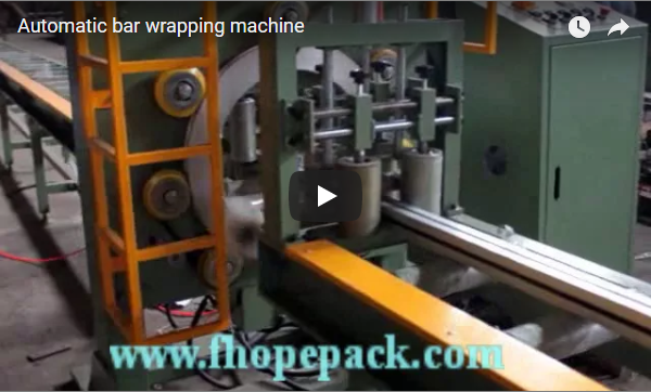
- Horizontal Ring Orbital Stretch Wrapping Machine Demo (Video)
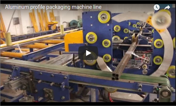
- Automatic Bundle Stacking and Packing System Integration (Video)
Sources
- FHOPE Engineering Technical Documentation: E-Series Orbital Stretch Wrapper Operating Manuals (2024).
- EN ISO 12100:2010 — Safety of machinery — Basic concepts, general principles for design.
- EN 415-10:2014 — Safety of packaging machines — Part 10: General requirements.
- EN 60204-1:2018 — Safety of machinery — Electrical equipment of machines — Part 1: General requirements.
- The industrial horizontal orbital wrapping machine system displayed in the embedded documentation above.
Last reviewed: 2026-10-20