Executive summary
Rigid tubes, bars, and extruded profiles exit downstream cut-off saws or extrusion cooling tables as discrete single units, yet logistical freight dictates master bundle consolidation. Manual counting, nesting, and timber-batten strapping introduce severe bottlenecking, piece-count discrepancies, and surface friction galling on mill or anodised finishes. An automated bundling and orbital stretch packaging system integrates singulation, indexing, mechanical forming, and continuous orbital film containment into a unified inline cell. This technical bulletin details the line architecture, kinematic parameters of the FHOPE E200 orbital wrapper, mathematical models for calculating bundle circumscribed diameter from piece count, and procurement selection criteria.
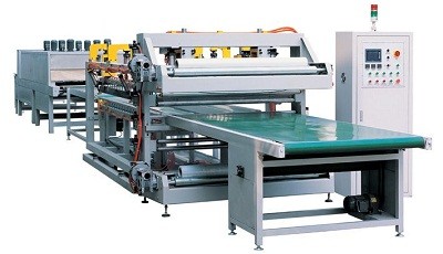
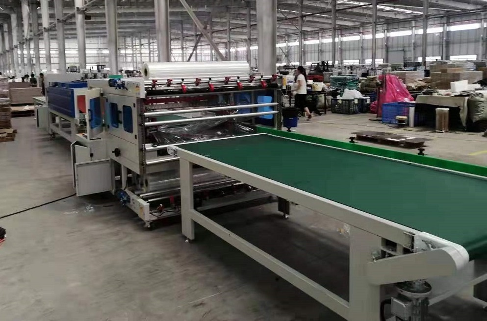
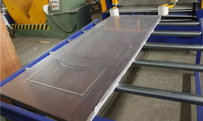
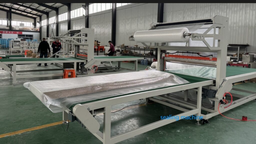
The integrated packaging cell automates the transfer of extruded aluminium profiles via polyurethane-lined cross-transfer chains, precisely collating pieces into an adjustable forming pocket before driven polyurethane infeed rollers transfer the bound bundle through an orbital ring wrapper for high-tension film encapsulation. Centralised HMI automation coordinates piece feeding, pneumatic clamp positioning, and rotary ring speeds to maintain structural integrity across delicate bundles.
Table of Contents
- Why bundle and pack in one continuous line
- How the automated packaging line works
- FHOPE E200 orbital wrapper technical data
- Calculating bundle dimensions from piece count
- Engineering selection checklist
- Machinery safety and compliance
- Engineering FAQ
- Next step and proposal request
- Related reading
- Sources and technical references
Why bundle and pack in one continuous line
Decoupling bundle collating from protective wrapping introduces acute handling vulnerabilities in high-throughput profile mills:
- Elimination of Count Drift: Transferring unsecured, loose bundles between standalone nesting racks and secondary strapping stations inevitably causes manual tally errors and piece migration. Inline mechanical counting establishes verifiable, digital recipe validation.
- Surface Integrity Protection: Repeated manual stacking, timber dunage levering, and loose sliding generate rub marks, abrasive fretting, and galling on architectural anodised, powder-coated, or polished aluminium finishes. Synchronised PU-cushioned transfer arms secure each workpiece without metal-to-metal rubbing.
- Retention of Dynamic Nesting Geometry: Gravity and chain-driven shaping guides lock tubes into round, square, or hexagonal arrays. Applying rotary stretch film directly at the discharge of the forming pocket freezes the bundle geometry under radial hoop tension before handling shocks can collapse the stack.
- Direct Labor Elimination: A single automated cell replaces 2 to 3 operators dedicated to manual counting, banding, and stretch wrapping, eliminating continuous saw-discharge line bottlenecks.
How the automated packaging line works
[ Extruder / Cut-Off Saw ]
           │
           ▼
[ 1. Infeed Roller Table ] ── (Accumulation & Axial Alignment)
           │
           ▼
[ 2. Indexing Chain Transfer ] ── (Singulation, Optical Counting & Sorting)
           │
           ▼
[ 3. Pneumatic Forming Station ] ── (Pocket Collating: Round / Square / Hexagon)
           │
           ▼
[ 4. Powered Conveyor System ] ── (Infeed Clamp & Top-Hold Down Stabilization)
           │
           ▼
[ 5. Orbital Ring Wrapper (E200) ] ── (Rotary Pre-Stretch Film Encapsulation)
           │
           ▼
[ 6. Outfeed & Downstream Cells ] ── (Intermediate Strapping / Bagging / Offload)- Infeed & Alignment: Extruded lengths arrive directly from the saw runout table onto driven polyurethane rollers that register and align tube leading ends against an adjustable datum stop.
- Indexing & Singulation: Flat-top transfer chains fitted with polymer lugs lift profiles individually from the drop zone. Photoelectric retro-reflective sensors verify piece presence and count against the target PLC recipe.
- Nesting & Forming: Singulated tubes drop sequentially into an adjustable mechanical pocket. Side guides, driven by pneumatic cylinders or manual handwheels, compress and settle the batch into a dense round, square, rectangular, or nested hexagonal configuration.
- Bundle Infeed Conveyance: Pneumatically actuated top-hold-down rollers clamp the unbundled matrix. Driven V-groove or flat cylindrical rollers move the compact bundle axially into the wrapper throat.
- Orbital Encapsulation: The rotating ring drives a film carriage around the continuously translating bundle. Mechanical friction or electronic pre-stretch tension units wrap LLDPE stretch film (or crepe paper/VCI) at pre-selected helix overlaps (10% to 90%).
- Automatic Cut, Clamp, and Outfeed: An integrated pneumatic cutter cleanly severs and wipes the film tail against the bundle body. The encapsulated bundle discharges onto an outfeed gravity or driven roll conveyor for offline bundling, downstream PET strapping, or bundling bag insertion.
FHOPE E200 orbital wrapper technical data
The FHOPE E200 horizontal orbital stretch wrapper provides primary wrapping for small-to-medium bundles, rod clusters, and single extrusions:
| Operational Parameter | Specification Metric (E200 Standard Configuration) |
|---|---|
| Package Outer Cross-Section (OD) | 50 mm minimum to 200 mm maximum |
| Usable Package Length | 1,000 mm minimum to custom runout maximum |
| Payload Weight Range | 8 kg to 100 kg (standard conveyor bed capacity) |
| Infeed & Outfeed Conveyors | Twin 2,000 mm powered conveyor tables (V-roller or Flat) |
| Linear Conveying Velocity | 6 m/min to 12 m/min (VFD-regulated speed synchronisation) |
| Ring Rotational Speed | Up to 150 RPM (variable frequency vector control) |
| Film Overlap Range | 10% to 90% (programmable via carriage and line speed ratio) |
| Wrapping Media Specifications | LLDPE cast stretch film, woven plastic ribbon, or VCI crepe paper |
| Film Roll Core & Width | Core ID: 50 mm / 76 mm; Film Width: 100 mm to 150 mm |
| Operating Safety Perimeter | Electro-welded safety mesh enclosures with interlocked access doors |
| Control System Architecture | Siemens or Delta PLC platform with touchscreen operator HMI |
Note: For bundle diagonals exceeding 200 mm, larger machine chassis (E300, E400, or E600 series) are engineered with corresponding ring IDs to accommodate target clearances.
Calculating bundle dimensions from piece count
Selecting the correct orbital wrapper ring frame requires matching the bundle’s maximum circumscribed envelope against the wrapper ring clear throat aperture.
The ring must accommodate the absolute outer diagonal, incorporating safety clearance for profile straightness deviations and film carriage traverse:
D_ring ≥ D_circumscribed + Clearance Margin(Where a minimum clearance margin of 30 mm to 50 mm is mandatory to prevent mechanical strikes during high-speed rotation).
      SQUARE BUNDLE GEOMETRY                HEXAGONAL BUNDLE GEOMETRY

      ┌───┬───┬───┬───┬───┐                     ╭───╮   ╭───╮   ╭───╮
      │ O │ O │ O │ O │ O │ H                ╭───╮   ╭───╮   ╭───╮   ╭───╮
      ├───┼───┼───┼───┼───┤               ╭───╮   ╭───╮   ╭───╮   ╭───╮   ╭───╮
      │ O │ O │ O │ O │ O │               │ O │ O │ O │ O │ O │ O │ O │ O │ Corner
      ├───┼───┼───┼───┼───┤               ╰───╯   ╰───╯   ╰───╯   ╰───╯   ╰───╯   Width
      │ O │ O │ O │ O │ O │                  ╰───╯   ╰───╯   ╰───╯   ╰───╯
      └───┴───┴───┴───┴───┘                     ╰───╯   ╰───╯   ╰───╯
            W (Width)                                Flat-to-Flat
      Diagonal = W × √2                     Width ≈ (2n - 1) × Piece OD
1. Square Matrix Formations
For symmetrical square configurations where N_row equals the number of pieces across the base:
- Bundle Width (
W):W = N_row × Tube_OD - Bundle Height (
H):H = N_row × Tube_OD - Total Piece Count (
Q):Q = (N_row)² - Circumscribed Diagonal Diameter (
D_diag):D_diag = W × √2 ≈ W × 1.4142
Engineering Calculation Example: For a 25 mm OD tube configured in a 5 × 5 square bundle (25 total units):
W = 5 × 25 mm = 125 mmD_diag = 125 mm × 1.4142 ≈ 176.8 mm- Ring Sizing Verification: 176.8 mm fits within the 200 mm maximum package diameter of the E200. However, a 6 × 6 bundle of the same 25 mm tube yields
W = 150 mm, givingD_diag = 150 mm × 1.4142 ≈ 212.1 mm. This exceeds the E200 aperture and mandates scaling up to an E300 model.
2. Regular Hexagonal Bundling (Honeycomb Nesting)
Dense hexagonal bundling provides maximum geometric stability under stretch film hoop stress. For a hexagon having n tubes along each outer side edge:
- Total Piece Count (
Q_hex):Q_hex = 3n(n − 1) + 1 - Max Dimension Across Corners (
D_corner):D_corner ≈ (2n − 1) × Tube_OD - Dimension Across Flats (
D_flat):D_flat ≈ [1 + (n − 1) × √3] × Tube_OD
Engineering Calculation Example:
For a hexagonal bundle with n = 4 pieces per edge using 25 mm OD tube:
Q_hex = 3 × 4 × (4 − 1) + 1 = 37 piecesD_corner ≈ (2 × 4 − 1) × 25 mm = 175.0 mm- Ring Sizing Verification: 175 mm falls within the E200 processing window.
Engineering selection checklist
Prior to specifying ring diameter, chain pitch, and handling kinematics, establish the following project baseline parameters:
- Piece Profile Geometry: Tube OD, wall thickness, or detailed CAD profile cross-section (W × H) and cut length range (minimum/maximum mm).
- Bundle Envelope Targets: Target pieces per bundle, required packing configurations (square, hex, or flat layer), and maximum bundle gross weight (kg).
- Upstream Cycle Rate: Profile exit speed from the cooling table or pieces-per-minute cycle time of the cold cut saw.
- Packaging Media Specification: Primary containment film (LLDPE stretch film gauge 20–35 µm), VCI anti-corrosion barrier, or heavy neutral crepe paper.
- Downstream Unitising Modules: Requirement for secondary PET/Steel strapping heads, inline polyethylene sleeve bagging, or robotic master palletising.
- Surface Sensitivity Grade: Verification of raw mill finish, architectural anodising, high-gloss electrophoresis, or powder coating to specify polyurethane, UHMW-PE, or nylon roller coverings.
Machinery safety and compliance
FHOPE automated bundling and wrapping cells are engineered in strict compliance with harmonised European safety norms and industrial standards:
- Risk Assessment & Design Principles: Certified to EN ISO 12100:2010 for holistic system hazard mitigation.
- Packaging Machine Functional Safety: Fully compliant with EN 415-10:2014, governing specific safety requirements for horizontal orbital stretch wrappers, including automatic feed, cut, and clamp mechanisms.
- Electrical Safety and Architecture: Built to EN 60204-1:2018, featuring IP54-rated industrial cabinets, 24 V DC control circuits, safety relays (PLe / Category 4 rated), and emergency stop interlocks.
- Physical Isolation: Fully enclosed by electro-welded perimeter mesh guarding with category-rated interlocked service gates to prevent human intrusion into the dynamic path of the orbital ring.
- Dynamic Motion Damping: Programmable variable frequency drives (VFD) govern S-curve acceleration and deceleration profiles, preventing mechanical bundle displacement during rapid starts or unexpected line e-stops.
Engineering FAQ
Q: Can this automated line process non-circular or asymmetrical profiles? A: Yes. Extruded rectangular hollow sections, window channel profiles, and solid flats are accommodated. Custom-machined polyurethane forming blocks, adjustable lateral pneumatic pushers, and recipe-driven servo guides nest asymmetrical sections reliably.
Q: Can the bundling line sync directly with a flying cut-off saw? A: Yes. The system receives cycle handshake signals (dry contact or Profinet/EtherNet/IP) from upstream saw discharge rolls, buffering single extrusions onto the indexing chain without backline interference.
Q: Does orbital stretch wrapping provide adequate rigidity, or is strapping mandatory? A: For short-to-medium bundles under 50 kg, high-tension stretch film with a high overlap ratio (50%–70%) yields sufficient containment rigidity for warehouse storage. For heavy industrial bundles or export transit, an inline automatic strapping unit should be positioned downstream to apply PET or steel bands directly over the pre-wrapped bundle.
Q: Can the E200 orbital wrapper be retrofitted to an existing manual packaging station? A: Yes. The E200 wrapper operates as an autonomous wrapping cell equipped with independent optical sensors, driven infeed/outfeed conveyors, and an independent control sub-panel, allowing seamless inline placement at the exit of legacy collating racks.
Next step and proposal request
To receive an equipment proposal and 2D/3D general layout drawing for your finishing bay:
- Submit Product Specs: Email your profile dimension drawings, target bundle counts, finished bundle lengths, and extrusion discharge rates to info@fhopepack.com.
- Engineering Assessment: Our project team validates orbital ring throat margins, conveyor loading capacities, and indexing drive cycles.
- Formal Turnkey Quotation: Receive a detailed commercial proposal, mechanical layout, and cycle rate analysis within 24 hours.
Related reading
- E200 horizontal stretch wrapper (product)
- Horizontal full-auto aluminium rods and profiles wrapping machine (video)
- Automatic bundle making and film binding machine (video)
- Aluminum profile bundle bag packing machine (video)
Sources and technical references
- FHOPE Engineering Technical Documentation: E200 Horizontal Orbital Wrapper Operation & Kinematics Manual.
- ISO Standards: ISO 12100:2010 Safety of machinery — General principles for design — Risk assessment and risk reduction.
- European Committee for Standardization: EN 415-10:2014 Safety of packaging machines — Part 10: General requirements.
- IEC Standards: IEC/EN 60204-1:2018 Safety of machinery — Electrical equipment of machines — Part 1: General requirements.
- Engineering Project Archive: Automated Extrusion Collating, Packaging and Stretch Encapsulation System Data.
Last reviewed: 2026-10-20