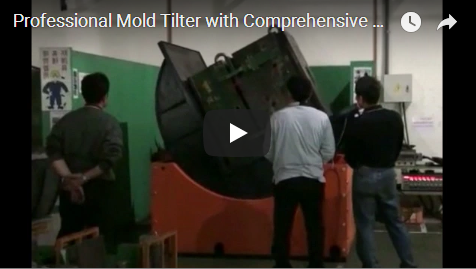
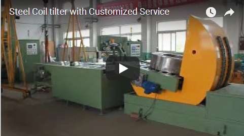
steel sheet pallet inverter

Executive summary This video shows a yellow steel sheet pallet inverter with a large C-shaped clamping arm that rotates a full stack of steel sheets from a vertical closed position through roughly 180° into an inverted, unload-ready position. An operator controls the whole cycle from a handheld remote while standing clear of the machine. A second, empty-run sequence shows the hydraulic drive and scissor-style support mechanism completing the full rotation and closing into a stable clamping position. Load ratings, cycle time, and model details are not shown — verify these with the manufacturer.

What the video shows

The footage runs about 108 seconds and is best understood as two sequences: a loaded inversion cycle (roughly the first minute) and an empty clamping/positioning demonstration (the remainder).

Approx. time What happens on screen
0–8 s Operator in a white hard hat and blue workwear stands beside the yellow machine holding a handheld remote. The machine is at rest: C-shaped clamping arm above, blue base below. A green oil drum sits at the right of frame.
12–20 s The C-shaped clamping arm begins rotating, turning about 90° from a vertical closed position toward a horizontal open posture. The operator steps back, still holding the remote.
24–32 s The arm continues rotating toward roughly 135°. Between the upper and lower jaws, a multi-layer stack of flat sheets — consistent with steel sheet — is clearly held in the clamp.
36–44 s The arm rotates further, approaching 180°. The sheet stack tilts as a whole toward the operator’s side. A second worker in a yellow hard hat enters from the right.
48–56 s The arm finishes its rotation to a near-vertical open state. The stack is now essentially inverted, hanging free of its original position, ready for unloading.
60–88 s A second demonstration begins with no product present. The large yellow frame rotates from a tilted, near-vertical dumping posture back toward horizontal, driven by visibly extending red hydraulic cylinders.
92–104 s The rotation completes. The upper carrier closes onto the lower base, forming a two-tier platform structure. The machine settles into a stable clamping state.
~108 s Final frames: machine holds its closed clamping position; the scene is static.

Two things stand out for anyone evaluating this type of equipment. First, the entire loaded inversion is executed by the machine’s own rotation plus gravity — no external conveyor or robotic arm participates. Second, the operator never touches the load during the turn; his role is to clamp, observe from a distance, and monitor.

How the machine is built

Based on what is visible in the frames, the machine consists of the following main elements:

Component Observation Apparent function
Main frame Bright yellow painted steel structure with visible weld seams and bolted joints Carries the rotating clamping assembly
Base Dark blue/black painted box-type steel base, with traces of guide rails on the floor Supports the whole machine and its rotation
C-shaped clamping arm Large arm with upper and lower jaws (pads) Grips the sheet stack during rotation
Hydraulic drive Red cylinder bodies with silver piston rods, black hoses routed along the arm Powers the flip/rotation motion
Scissor-type support X-shaped linkage visible between upper and lower carriers (second sequence) Vertical positioning of the upper carrier
Control elements Red button and green indicator light on the base front; white label (unreadable); no screen visible Basic local control and status indication
Handheld remote Wireless unit held by the operator Remote operation of the cycle

The machine’s overall height is estimated at roughly 2.5–3 m with a base width of about 2 m, based on comparison with the operator. These are visual estimates only — confirm exact dimensions with the manufacturer.

Direct observation notes

The block below stays close to the source report’s factual statements; only grammar-level edits have been applied.

  • A worker wearing a white safety helmet and blue work clothes stands at the left of a large yellow machine, holding a remote control. The machine is stationary, with a C-shaped clamping structure on top and a blue base below.
  • The machine begins to move: the C-shaped clamping arm rotates rightward about 90°, from a vertical closed position to a horizontal open posture; the worker steps back one pace, still observing with the remote.
  • Between the upper and lower jaws, a multi-layer stack of flat sheets (apparently steel sheet) is clamped.
  • The clamping arm continues rotating upward to approximately 180°, tilting the sheet stack as a whole toward the operator’s direction.
  • The arm completes the flip to a near-vertical open state; the sheets have largely left their original position, in an inverted, suspended posture.
  • In the second sequence, the machine is empty: red hydraulic cylinders extend noticeably as the frame rotates back toward horizontal; a scissor-type mechanism between the carriers performs vertical positioning; the upper and lower carriers close into a two-layer clamping platform.
  • The control area shows at least one red button and one green indicator light; no digital display or touchscreen is visible.
  • No fixed safety fence, light curtain, or clearly readable warning signage is observed; readable text in the scene is limited to lettering on a green oil drum at the side of the frame.
  • Operators keep a distance of roughly 1.5 m or more from the machine while it moves.

What the video does not show

Buyers should be aware of the clear evidence boundary. The video does not show:

  • Rated load capacity — the maximum weight and sheet thickness the machine can invert.
  • Cycle time — a full cycle’s start and end cannot be confirmed from sampled frames.
  • Machine model name and technical specifications (motor power, hydraulic pressure, drive ratios).
  • Safety certifications (CE, ISO, or equivalent marks).
  • Control system details — PLC or drive brand, no screen interface.
  • Precise rotation angle limits — the ~90°/135°/180° values are visual estimates.
  • Automation features — no automatic detection, stack-alignment alarm, or anti-error function is demonstrated.
  • Operating manual content, maintenance intervals, or fault-code documentation.

None of these points should be assumed from the footage. Verify with the manufacturer before any purchase decision.

Why this machine type matters

For plants handling stacked steel sheet, the inversion step — turning a palletized or stacked load over — is traditionally done with forklifts, cranes, or manual labor, all of which carry damage and injury risk. A dedicated inverter like the one shown replaces that handling with a controlled mechanical rotation.

Derived from the footage (clearly labeled as inference, not video fact):

  • Reduced manual handling. The operator only clamps and monitors; the machine does the turning. This removes workers from the heaviest part of the job.
  • Gravity-assisted, lower-impact turning. The stack rotates with the arm and settles under gravity into the unload position, which reduces shock compared with rough forklift-based turning.
  • Consistent, repeatable motion. The hydraulic drive and guided structure produce the same rotation path each cycle, which matters when sheets must not shift or scratch.
  • Simple operation. A single operator with a wireless remote runs the cycle from outside the swing radius — no cabin, no complex interface visible.

Known limitations visible in or inferred from the footage: unloading after inversion still depends on manual or downstream equipment; the video shows no real-time feedback such as torque monitoring or position calibration; and no guarding or light curtain is visible on site. All of these are points to raise with the supplier.

Safety notes for operators

The video shows a working arrangement, not necessarily a complete safety package. Treat the following as baseline practice:

  1. Keep all personnel outside the arm’s rotating radius during the cycle. The operators in the video maintain a distance of roughly 1.5 m or more.
  2. Never reach toward the jaws or the load while the arm is in motion — the entire swing path is a hazard zone.
  3. Confirm the location and function of the emergency stop before first use. A red button is visible on the base; whether it is a true emergency stop and whether the remote carries one — verify with the manufacturer.
  4. Inspect hydraulic hoses and fittings regularly. The hoses are routed along the moving arm and are subject to flexing every cycle.
  5. Ensure the load is centered and gripped fully between the jaws before starting rotation; an off-center stack increases tipping risk.
  6. Because no fence or light curtain is visible in the footage, ask the supplier what guarding, alarms, or interlocks can be supplied or what site-side measures they recommend.

What to verify with the manufacturer

Before ordering, put these questions in writing:

# Question Why it matters
1 What is the rated load capacity, and does it match our sheet thickness, width, and stack count? The video gives no load data at all.
2 What is the actual rotation angle and full cycle time? Frame-based estimates are not specifications.
3 Are emergency stop, limit switches, and anti-drop protection included? No independent e-stop was clearly identifiable on screen.
4 Can the machine connect to a PLC or plant system (e.g., for line integration)? No interface or screen is shown.
5 What certifications apply (CE or regional special-equipment rules)? No certification marks are visible.
6 What are the maintenance schedule and spare parts arrangements? Hose and seal condition directly affects uptime.

Frequently asked questions

Can this inverter handle a full stack of steel sheet in one cycle? The video shows one full stack gripped and inverted in a single rotation. Whether your stack weight and dimensions fit within capacity — check with the manufacturer; no load figures appear in the footage.

Is loading and unloading automatic? No. The footage shows the machine inverting the stack, with workers nearby handling the surrounding steps. No conveyor or robotic loading is shown.

How does the operator control the machine? With a handheld wireless remote. The operator stands away from the machine for the whole cycle. Local buttons and an indicator light are also visible on the base; a screen is not.

Does the machine need a foundation or special floor? Guide-rail traces are visible on the floor near the base in the second sequence. Foundation or anchoring requirements — verify with the manufacturer.

What happens after the stack is inverted? The inverted stack hangs in an unload-ready position, awaiting manual or mechanical removal. Downstream handling is not shown in the video.

Where this fits in a packing or handling line

A sheet-stack inversion is usually one step in a longer flow. Upstream, stacks arrive from pressing or storage; downstream, the flipped stack may be wrapped, strapped, or transferred. If your process continues after inversion, it is worth reviewing complementary equipment on the same site, such as the semi-automatic pallet wrapping machine or the automatic pallet wrapping machine for securing loads after handling, and the automatic steel tube packing line as an example of how individual machines integrate into a full line.

Buying checklist

Use this quick list before requesting a quotation:

  • Measured stack weight, sheet thickness, width, and length recorded
  • Required rotation angle and target cycle time defined
  • Floor space and swing radius at the installation site confirmed
  • Power supply and hydraulic requirements clarified with the supplier
  • Safety package (e-stop, guarding, interlocks) specified in the order
  • Training and maintenance documentation included in delivery

Related reading

Next step

If the handling challenge in this video matches yours — heavy stacked steel sheet that needs turning over safely and consistently — the next step is a conversation about your exact stack size, weight, and workflow. Contact the FHOPE team through the contact page to discuss configuration, capacity, and integration options.


Source and method. This article is based solely on the embedded video. The footage was analyzed frame-by-frame using a vision model on sampled frames (28 frames at 4-second intervals); the video contains background music only, with no narration or speech, so no transcript was used. All observed details come from the frames; all evaluations and limitations are explicitly labeled as inference; all load, cycle, and specification figures are unobserved and marked for verification with the manufacturer.

Published: 2026-09-03

Published: 2026-09-03