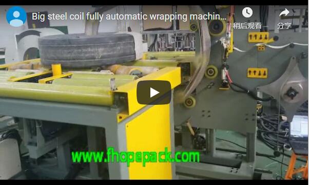
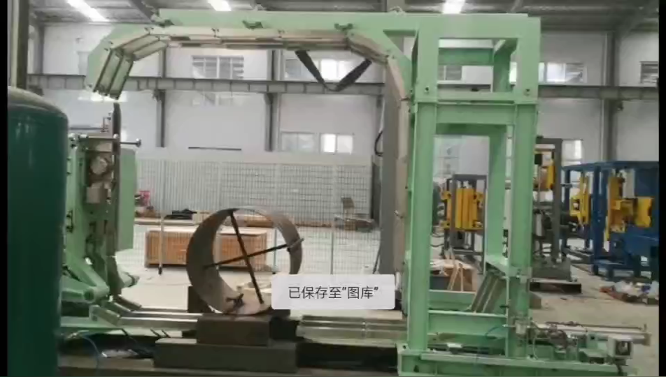
Summary: This technical protocol equips field engineers to inspect, operate, and maintain steel coil wrapping and packing systems with a focus on safety interlocks, film tension stability, structural capacity, and commissioning readiness. Use it to verify new or existing equipment before shipping compliance audits.
[VIDEO PLACEHOLDER]
🛠️ System Architecture & Commissioning Verification
Validate structural load ratings against the 500–3500 kg reel capacity envelope before energizing control circuits. Cross-reference PLC I/O mapping with physical wiring schematics and verify pneumatic regulator stability within OEM-specified tolerances to ensure baseline mechanical integrity.
-
Frame structural verification: Inspect the Q355B steel chassis for weld discontinuities, stress fractures, or base plate deformation. Dynamic load capacity must align with the 500–3500 kg reel weight range; verify per OEM manual or typical range for site-specific coil masses.
-
PLC controller & I/O validation: Confirm the programmable logic controller firmware matches the physical terminal block layout. Remote support hours vary by vendor contract; schedule a dedicated session to validate I/O mapping, safety logic, and parameter table backups.
-
Servo tension calibration: Measure film tension using a calibrated load cell. Acceptable accuracy is typically ±4–6 N under continuous operation; verify per OEM manual or typical range. Record baseline values at three distinct points along the wrap cycle to establish a tension drift benchmark.
-
Safety interlock circuit validation: Test all emergency stop circuits, light curtains, and zero-speed detection switches. Response thresholds must comply with applicable local directive language rather than fixed millisecond targets. Each interlock must interrupt machine motion and trigger a fault state upon activation.
-
Pneumatic regulator stability: Set pressure regulators to factory specifications (typically 0.5–0.7 MPa) and monitor stability during film advance and retract cycles. Record fluctuation ranges; deviations exceeding ±0.02 MPa indicate filter saturation or regulator wear.
🏗️ Operational Parameters & Material Integration
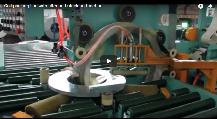
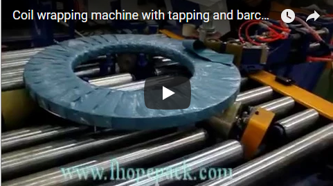
Execute two-layer synchronous winding with internal threading using LLDPE, PVC, or HDPE films calibrated to exact coil dimensions. Synchronize orbital speed and band tension with destination-specific corrosion and mechanical protection requirements to maintain wrap consistency across variable load profiles.
-
Coil surface preparation: Ensure the coil surface is free of machining oil, mill scale, and particulate debris before loading. Use industrial-grade wipes or filtered compressed air; residual contaminants compromise film adhesion and accelerate corrosion under wrap.
-
Material selection & dimensional alignment: Select packaging film based on coil weight, transport mode, and environmental exposure. Standard dimensions require an inner diameter of 50 mm and a width of 100–120 mm. LLDPE/PVC outer diameters typically range 100–150 mm, while HDPE accommodates 200–350 mm OD. Verify per supplier guidelines for thickness and tensile modulus.
-
Machine parameter configuration: Input exact coil geometry into the HMI. Confirm that the wrapping ring orbital speed does not exceed rated RPM (typically 30–40 rpm for standard systems). Synchronize the two-layer synchronous winding with internal threading to prevent film overlap gaps or excessive tension buildup.
-
Film tension monitoring: During initial wrap cycles, track the tension display against the calibrated baseline. Servo positioning tolerance should remain within ±0.2–0.3 mm; deviations exceeding 6 N require immediate recalibration. Wrap consistency directly correlates to moisture and rust protection efficacy.
-
Band securing & load distribution: After wrapping, apply steel or plastic bands at prescribed intervals (typically every 200–300 mm along coil width). Verify band tension with a handheld tensiometer (target range 200–400 N). For maritime transport, integrate a multi-layer process: inner polyethylene film, wooden crate containment, and steel band reinforcement.
🔗 Related: Explore more solutions
📈 Preventive Maintenance & Component Lifecycle
Implement scheduled bearing replacement, guide roller alignment, and linear rail lubrication intervals to prevent cumulative wear-induced tension drift. Monitor electrical cabinet thermal loads and pneumatic filtration status to maintain servo responsiveness and extend component service life.
-
Bearing replacement protocol: Tool-free bearing replacement should be executed within 30–40 minutes per OEM guidelines. Time the replacement during scheduled downtime to avoid unplanned OEE loss. Document bearing part numbers and installation torque values.
-
Guide roller alignment & wear inspection: Check guide roller surface integrity using a precision straight edge. Replace rollers if surface roughness exceeds 0.1 mm over a 100 mm span. Lubricate all access points according to the manufacturer’s grease schedule to prevent film tracking errors.
-
Film carriage lubrication: Inspect linear rails and ball screws for grease distribution and particulate contamination. Reapply lithium-based grease every 500 operating hours or at quarterly intervals, whichever occurs first. Degraded lubrication directly impacts servo positioning accuracy.
-
Electrical cabinet thermal management: Confirm cabinet ventilation fans are operational and intake filters are free of dust accumulation. Measure internal temperature during peak operation; thermal loads must remain below 45 °C. Excessive heat accelerates capacitor degradation and PLC component fatigue.
⚠️ Manufacturer Tolerance Disclaimer: Tension pressure, pneumatic operating ranges, and ambient temperature tolerances are variable and must be cross-referenced with the specific equipment OEM manual. Field engineers must validate all mechanical and electrical thresholds against site-specific load profiles and environmental conditions before commissioning.
🛡️ Safety Compliance & Pass/Fail Documentation
Enforce lockout-tagout protocols when interlock circuits breach response thresholds defined by applicable local directive language. Document all calibration deviations, material substitutions, and corrective actions against verifiable OEM manuals and third-party calibration certificates to satisfy audit requirements.
-
Emergency stop circuit verification: Activate each E-stop twice: once from the operator panel, once from the remote pendant. Machine must halt motion and display the corresponding fault code. Response timing must align with applicable local directive language.
-
Light curtain function testing: Interrupt the light curtain beam at three distinct vertical positions during active cycling. The system must immediately cease motion and require a manual reset sequence. Misalignment creates blind spots that bypass safety interlocks.
-
Acoustic environment assessment: Measure sound pressure at 1 m from the machine during full operational cycles. Thresholds must not exceed 85 dB(A) per typical industrial limits. Exceeding this threshold mandates hearing protection protocols or acoustic enclosure installation.
-
Operator manual & documentation audit: The OEM manual, including wiring diagrams, maintenance schedules, and parameter tables, must be physically present on-site. Confirm the documentation matches the exact serial number and configuration installed.
Pass/Fail Verification Matrix
| Checklist Item | Pass Condition | Fail Condition |
|---|---|---|
| Frame structural check (Q355B) | No cracks; load capacity ≥500 kg and ≤3500 kg (dynamic) | Any weld discontinuity, deformation, or capacity mismatch |
| PLC wiring match | I/O map corresponds 1:1 to physical connections per OEM schematic | Any mismatch or undocumented parameter modification |
| Servo tension accuracy | ±4–6 N across three measurement points (verify per OEM manual or typical range) | Deviation >6 N in any point or uncalibrated load cell |
| SIL2 safety interlock | All E-stops, light curtains, and zero-speed detectors respond per applicable local directive language | Breach of response threshold or incomplete circuit isolation |
| Pneumatic pressure stability | Fluctuation ≤0.02 MPa during cycle | Fluctuation >0.02 MPa or pressure outside factory specification |
| Material selection correctness | Film type matches coil weight, OD, and destination protection requirements | Incorrect film type, insufficient layers, or unverified thickness |
| Wrapping tension positioning | ±0.2–0.3 mm servo tolerance maintained across cycle | Tolerance >0.3 mm or visible film overlap/gap defects |
| Band tension | 200–400 N per calibrated tensiometer | 400 N, or inconsistent band spacing |
| Bearing replacement time | ≤40 minutes per OEM guidelines | >40 minutes or improper torque/fastener sequence |
| Guide roller wear | Surface roughness ≤0.1 mm over 100 mm span | Roughness >0.1 mm, visible grooves, or tracking deviation |
| Cabinet temperature | <45 °C during peak operation | ≥45 °C or non-functional ventilation/filtration |
| Noise level | ≤85 dB(A) at 1 m operational distance | >85 dB(A) without hearing protection or enclosure |
Key Point: If any safety interlock or structural component fails verification, the machine must be locked out immediately. Document all failures, corrective actions, and third-party calibration certificates in the site maintenance log to satisfy compliance audits.
🔗 See Also: Related equipment
⚙️ Frequently Asked Questions
Q: How often should I calibrate the servo tension controller?
A: Calibrate every 1,000 operating hours or whenever tension deviation exceeds ±6 N. Use a reference load cell certified to ±0.5 N accuracy. Verify calibration intervals per OEM manual or typical range based on duty cycle intensity.
Q: What is the minimum wrapping layer count for overseas shipping?
A: Industry standard requires a two-layer synchronous winding with internal threading. For maritime transport, integrate an inner polyethylene film layer, a wooden crate, and steel band reinforcement. Film thickness is variable; cross-reference with supplier guidelines or mark as variable per logistics requirements.
Q: Can I use HDPE film for all coil weights?
A: HDPE is structurally suitable for coils up to 3,500 kg when paired with a servo-controlled tension system. For lighter reels or higher elongation requirements, LLDPE or PVC (OD 100–150 mm) may be optimized. Verify film selection with your material supplier and site load profile.
Q: How do I handle PLC parameter drift during remote support?
A: Remote support hours vary by vendor contract. All parameter adjustments must be logged in the site commissioning book with timestamps, original values, and revised setpoints. Maintain a factory backup of the baseline PLC file before any remote intervention.
Q: What documentation is required for pass/fail audit compliance?
A: All pass/fail criteria must reference verifiable documentation, including OEM installation manuals, third-party calibration certificates, pneumatic pressure logs, and safety interlock test records. Unverified field measurements are insufficient for compliance sign-off.
🛡️ Compliance Note: This equipment is designed to meet ISO and ASTM requirements. Verify specific certifications with the manufacturer before procurement.