Executive summary
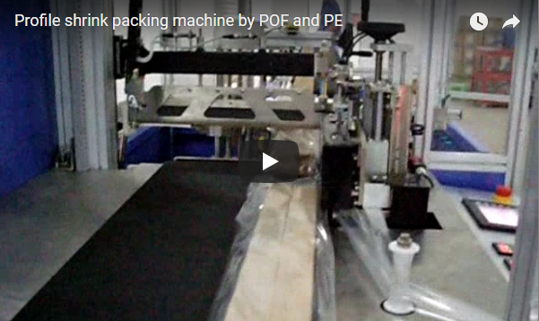
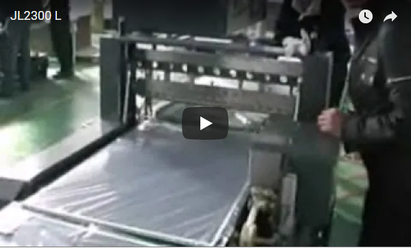
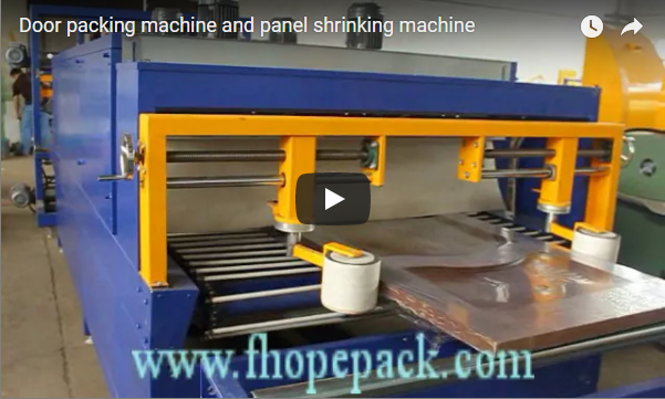
A panel shrinking machine seals an individual panel or an entire stack of rigid boards in low-density polyethylene (LDPE) shrink film and conveys it through a forced-air convection tunnel, forming a fully enclosed, puncture-resistant protective sleeve. Engineered specifically for insulation boards (XPS, EPS, PIR), wood-composite architectural panels, entry doors, and modular cabinetry components, this continuous motion-sealer line accommodates pack profiles up to 1,250 mm wide, 2,500 mm long, and 10–90 kg in mass. Running 30–45 µm mono-oriented or biaxially oriented PE film through a 2,600 mm recirculating thermal chamber at line velocities up to 12 m/min, the system delivers hermetic edge containment without slowing down product flow. The technical operational breakdown, upstream gantry integration, machine specifications, and throughput calculations are detailed below.
Table of Contents
- Why shrink pack panels
- How the panel shrink line works
- Stacking and handling before sealing
- Machine data
- Worked example: a stack of foam boards
- Selection checklist
- Safety: EN 415-10 and ISO 12100
- Engineering FAQ
- Next step
- Related reading
- Sources
Why shrink pack panels
Finished panels and structural core boards present broad surface areas paired with delicate edge profiles. During transport and warehouse staging, standard mechanical damage occurs predominantly at corners and tongue-and-groove joints. Stacked sheets tend to experience micro-slipping (inter-layer scuffing), dry foam insulation crumbles under concentrated strap pressure, and fine airborne contaminants settle on face veneers intended for pristine downstream lamination.
A fully enclosed, heat-shrunk film package unifies the entire stack into a monolithic structural bundle. Unlike conventional horizontal stretch wrapping, thermal shrink packaging achieves full six-sided encapsulation. It eliminates trailing film tails, prevents moisture and UV ingress, and allows brand printing and barcode scanning through high-clarity LDPE film.
How the panel shrink line works
- Infeed Section: The raw panel or pre-squared stack transitions onto the heavy-duty powered infeed conveyor via upstream line integration or manual transfer.
- Dual-Roll Film Feeding: Upper and lower motorized film unwind stands deliver continuous sheeting over and under the advancing bundle, maintaining regulated film tension via dancer arm sensors.
- Continuous Sealing System:
- Side longitudinal sealers continuously weld and trim excess film along both product flanks.
- A servo-driven continuous motion cross-sealer tracks alongside the moving pack at matched line speed to complete the transverse hot-knife cut and seal cycle. Integrated photoelectric sensor arrays register the leading and trailing edges, dynamically modulating seal bar stroke and cycle height without halting conveyor momentum.
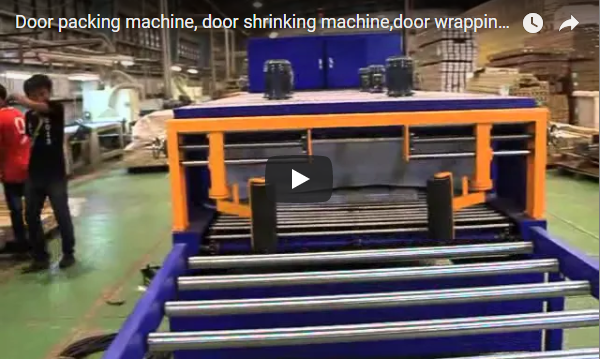
- Thermal Recirculation Shrink Tunnel: The bagged bundle enters a 2,600 mm double-insulated convection tunnel operating at 100–220°C. Centrifugal blowers circulate high-velocity hot air through adjustable bottom and side louvers, inducing uniform polymeric contraction across machine direction (MD) and transverse direction (TD). An inline air-knife cooling station rapidly cools the film upon exit to set the polymer skin rigidly.
- Outfeed and Discharge: Enclosed bundles exit onto an idle or motorized roller conveyor for robotic palletizing or automated strapping.
System control is handled by an industrial PLC with an HMI touch interface, storing heating curve profiles, encoder synchronization, and automated fault diagnostics across safety interlocks.
Stacking and handling before sealing
In insulation and drywall manufacturing, the packaging unit is almost exclusively a multi-layer stack rather than an isolated board. Upstream of the infeed section, an overhead gantry handling system equipped with vacuum suction pads or pneumatic side-clamps transfers stacked boards directly from the sizing line onto the conveyor bed.
Key mechanical handling considerations:
- Mechanical Squaring: Multi-panel stacks must pass through an automated pneumatic side-aligning pusher prior to the sealing station. Misaligned boards cause uneven film tension and crooked cross seals.
- Vertical Envelope Limitation: The total stack height must reside strictly within the vertical travel envelope of the cross-seal jaw and the tunnel clear opening.
- Edge Profiling Stability: For insulation panels engineered with shiplap or tongue-and-groove profiles, boards should be stacked with interlocking orientations to eliminate stack racking on high-speed transitions.
Machine data
| Parameter | Specification (Continuous Motion-Sealer Line) |
|---|---|
| Max Pack Width | 1,250 mm |
| Max Pack Length | 2,500 mm |
| Pack Weight Range | 10–90 kg |
| Max Pack Height | Determined by sealer jaw opening and tunnel clearance (customizable upon layout approval) |
| Packaging Film Material | LDPE / Polyethylene shrink film, 30–45 µm (0.030–0.045 mm) |
| Conveyor Speed Range | 0–12 m/min (variable-frequency drive regulated) |
| Sealing System Connected Load | Approximately 6.5 kW (PID solid-state relay control) |
| Shrink Tunnel Dimensions | L 2,600 mm × W 1,600 mm × H 1,300 mm |
| Tunnel Operating Temperature | 100–220°C (multi-zone recirculating air convection) |
| Standard Electrical Supply | 380 V, 50/60 Hz, 3-Phase (415 V / 480 V options available) |
Note: For lightweight standalone interior doors or thin architectural sheets (20–60 mm thickness), an economy intermittent-seal variant is available utilizing 30–80 µm film equipped with vertical side-tuck rollers to smooth peripheral excess.
Worked example: a stack of foam boards
To evaluate line capability, consider an extruded polystyrene (XPS) insulation board pack: individual board dimensions 1,200 mm (L) × 600 mm (W) × 50 mm (T), bundled 8 boards per stack, running at a nominal line speed of 6 m/min with a 0.5 m conveyor pitch spacing between consecutive bundles.
| Verification Step | Engineering Calculation | Line Assessment |
|---|---|---|
| Total Stack Height | 8 × 50 mm = 400 mm |
Clears standard vertical envelope |
| Planar Clearance | Length: 1,200 mm ≤ 2,500 mm; Width: 600 mm ≤ 1,250 mm |
Pass (centered on conveyor track) |
| Tunnel Residence Time | 2.6 m ÷ (6 m/min ÷ 60 s/min) = 2.6 ÷ 0.1 m/s |
26.0 s (sufficient for complete 35 µm PE contraction) |
| Cycle Pitch Time | (1.2 m pack + 0.5 m gap) ÷ (6 m/min ÷ 60 s/min) = 1.7 m ÷ 0.1 m/s |
17.0 s per unit cycle |
| Conveyor Conveyance Limit | 3,600 s/hr ÷ 17.0 s |
≈ 211 stacks/hr theoretical ceiling |
| Effective Net Capacity | 3,600 s ÷ max(17.0 s, Sealer Synchronized Return Cycle) |
Confirmed by factory servo sync test |
Kinematic Conclusion: The conveyor infrastructure supports up to 211 completed stacks per hour at 6 m/min. Because the motion-sealer carriage travels concurrently with the product during the sealing cut, the cross-seal cycle does not arrest the conveyor unless the carriage return stroke duration exceeds the 17.0-second pitch window. The combined mass of the stack (400 mm height XPS ≈ 18–25 kg) remains well inside the 10–90 kg roller loading threshold.
Selection checklist
- Dimensional Envelope: Minimum and maximum board length, width, individual thickness, and full stack height.
- Gross Mass & Substrate Density: Structural weight per bundle (verifying structural roller load ratings between 10 kg and 90 kg).
- Feed Automation Level: Standalone manual batch staging or continuous integration with an upstream sizing/cooling conveyor.
- Required Line Output: Required units per hour (determines tunnel length and whether motion sealing or stop-and-go sealing is warranted).
- Film Specification: Film grade, slip additives, puncture-resistance ratings, and micro-perforation requirements for trapped air egress.
- Auxiliary Downstream Modules: Integration of motorized cooling blowers, bundle turnover units, or end-of-line palletizing cells.
Safety: EN 415-10 and ISO 12100
Every industrial packaging line is designed and evaluated strictly in accordance with ISO 12100:2010 (Safety of machinery — General principles for design — Risk assessment and risk reduction) and EN 415-10 (Safety of packaging machines — Part 10: General requirements).
- Thermal Enclosure: The 2,600 mm heat tunnel features high-density rock wool thermal insulation, ensuring external sheet-metal casing temperatures remain strictly below touch-hazard thresholds.
- Motion Sealer Guarding: The synchronized flying cut-and-seal carriage is enclosed within interlocked physical barrier guards. Infeed and outfeed portals are secured via Type 4 optical safety light curtains that immediately drop drive torque upon perimeter interruption.
- Upstream Gantry Cells: The automated vacuum transfer gantry operates inside a dedicated wire mesh enclosure with dual-channel category 3 safety interlocks and localized Emergency Stop (E-stop) actuators.
Engineering FAQ
Q: Can the line package individual thin panels as well as high-density stacks? A: Yes. The PLC stores multiple product recipes. The photocell height-tracking system automatically calculates the appropriate vertical travel limit for the cross-sealing jaw, whether processing a single 20 mm door panel or a 400 mm stack of insulation boards.
Q: What prevents air pockets from ballooning inside the sealed film sleeve during shrinking? A: The film feed carriage includes mechanical cold-needle perforation rollers. These punch micro-perforations along the film edges, allowing expanding trapped air to escape rapidly inside the hot-air tunnel while maintaining complete structural seal integrity.
Q: Does the motion-sealer require the product stack to pause during the cross cut? A: No. Unlike stationary stop-and-go L-sealers, the motion cross-sealer carriage is mounted on linear servo rails. It accelerates to match conveyor surface speed, clamps, cuts, and seals the film on the fly, and then returns to home position, maintaining continuous line velocity.
Q: How is thermal degradation avoided on heat-sensitive foam panels (e.g., EPS/XPS)? A: Heating is achieved via indirect turbulent convective flow rather than direct radiant heat. Multi-zone digital controllers regulate air distribution dampers, ensuring air velocity surrounds the LDPE film without concentrating radiant heat onto the foam core.
Next step
- Submit Product Parameters: Forward your panel dimensions (L × W × H), stack configurations, pack weight range, and required line output to info@fhopepack.com.
- Technical Engineering Review: Our packaging application team reviews mechanical layout drawings, film gauge compatibility, and cycle kinetics.
- Formal Proposal Delivery: Receive a comprehensive line layout, budget proposal, and cycle-time guarantee within 24 hours.
Related reading
- Door shrinking machine with motion sealer (product)
- Economic type door shrink packing machine (product)
- Automatic panel sealing and shrinking machine
- Door and panel shrink packaging machine
- Orbital wrapping for extra-long panels
- Horizontal wrapping machine for glass door
Sources
- FHOPE Engineering Technical Documentation: Motion-Sealer Panel Packaging Series
- Machine operational protocols for continuous horizontal shrink film packaging lines
- ISO 12100:2010: Safety of machinery — General principles for design — Risk assessment and risk reduction
- EN 415-10: Safety of packaging machines — General requirements
Last reviewed: 2026-10-19