Sawn, planed, and profiled timber bundles face harsh conditions during open storage, flatbed road freight, and ocean shipping. Loose lumber packs absorb ambient moisture, suffer ultraviolet discoloration, and pick up road grime. When bundles shift during transit, strap slackening causes edge splintering and inter-layer friction.
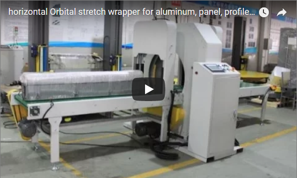
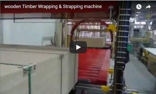
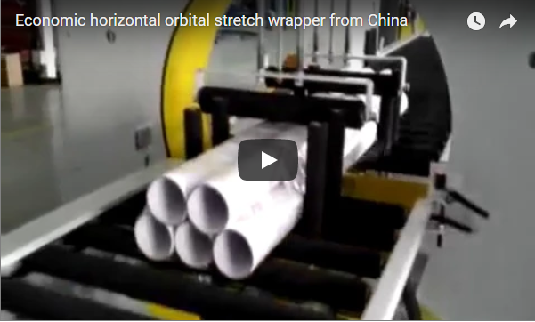
Continuous horizontal stretch wrapping binds loose lumber into a rigid unit by applying constant hoop tension around the pack. Pneumatic vertical press rollers clamp the timber before and after the wrapping plane to prevent layer shifting, while an aluminum ring wraps film around the load. The FHOPE E1000 processes diagonals from 400 to 1,000 mm at 3–12 m/min.
In this technical breakdown, I walk you through the structural envelope checks, film overlap math, integration points for dunnage and strapping, and production throughput limits.
Table of Contents
- Why do timber bundles need wrapping at all?
- What does the wrapping station consist of?
- What are the E1000 specifications?
- How do you check envelope and overlap for a 500 × 300 mm bundle?
- How does wrapping fit strapping, bearers, and edge protection?
- What should sawmill engineers specify?
- Which safety standards govern the line?
- What else do timber buyers ask?
- Conclusion
- Related Reading
- Sources and Reference Standards
Why do timber bundles need wrapping at all?
Wrapping timber bundles compresses individual boards into a rigid block that resists transport vibration and moisture ingress. High-clarity stretch film seals the wood against rain, dirt, and surface abrasion while permitting barcode scanning and timber grading without tearing the protective film envelope during storage and handling.
Helical stretch wrapping applies continuous radial tension that locks boards together. For dressed architectural lumber, decorative mouldings, and engineered flooring, stretch wrapping acts as a primary barrier against scuffing. It works together with polyester (PET) strapping to keep packages uniform during forklift handling.
Moisture management dictates the wrapping recipe:
- Green (Unseasoned) Timber: Freshly sawn lumber carries moisture content above 30%. Completely sealing unseasoned wood traps moisture, which leads to blue stain, mould, and internal rot. Operators run the wrapper with an extended pitch (20%–30% overlap) to create an open spiral wrap. Plants can also load macro-perforated stretch film, non-woven polypropylene, or breathable kraft paper.
- Kiln-Dried (KD) Timber: Dried to 12%–19% moisture content, structural timber and millwork require complete shielding from rain and humidity. Applying a high overlap of 50%–65% blocks water ingress and stops hygroscopic swelling during yard storage.
What does the wrapping station consist of?
The wrapping station relies on four primary mechanical sub-assemblies to stabilize variable lumber packs:
- Infeed and Outfeed Conveyor Systems: Variable frequency drive (VFD) flat belt conveyors or heavy-duty powered roller tracks feed bundles smoothly without marring the bottom faces. Lateral guide rollers center the lumber along the machine axis before it enters the ring.
- Pneumatic Vertical Clamp Units: Overhead press arms with non-marking polyurethane pads sit directly before and after the wrapping plane. Adjustable pneumatic pressure (0.2–0.5 MPa) suppresses vibration and prevents upper layer displacement under film tension. This controlled clamping protects soft wood species like radiata pine or spruce from localized surface crushing.
- Orbital Ring Assembly: A dynamically balanced cast-aluminum or machined-steel ring rotates on four heavy-duty polymer-faced support wheels within an enclosed structural frame. A VFD brake motor powers the ring through high-friction timing belts, providing smooth acceleration ramps and exact stops at the cut-and-clamp position.
- Mechanical Film Carriage and Delivery System: The dispenser mounts directly on the rotary ring and takes standard industrial rolls (100–500 mm roll width with 50 mm or 76 mm core). A mechanical friction pre-stretch brake with an indexed manual adjustment wheel allows operators to dial in tension between 50 N and 180 N. A pneumatic clamp and mechanical scissor or hot-wire cutting mechanism secures the film tail at cycle completion.
What are the E1000 specifications?
The FHOPE E1000 covers package diagonals from 400 mm to 1,000 mm, bundle lengths from 1,000 mm upward, and standard loads between 50 kg and 400 kg. With line speeds of 3–12 m/min and ring speeds up to 60 rpm, it fits intermediate to high-volume sawmill packaging operations.
Below are the standard technical specifications for the unit [manufacturer rating]:
| Parameter | Engineering Value | Operating Conditions / Notes |
|---|---|---|
| Passage Envelope Capacity | Diagonal: 400–1,000 mm; Length: ≥ 1,000 mm | Rectangular profile must sit inside the ring envelope clearance |
| Rated Bundle Weight | 50–400 kg | Up to 1,500 kg with upgraded heavy-duty roller conveyors |
| Infeed Conveyor | 2,000 mm length × 1,200 mm effective width | Continuous heavy-duty belt / VFD synchronized |
| Outfeed Conveyor | 2,000 mm length × 800 mm effective width | Extended support wings available for wider lumber packs |
| Conveyor Line Speed | 3–12 m/min (infinitely variable) | Regulated by line PLC to match overlap pitch |
| Ring Rotation Speed | 10–60 rpm (frequency controlled) | Soft-start / soft-stop ramp profile |
| Wrapping Consumables | LLDPE stretch film, PE film, Paper, Woven PP | Roll width: 100–500 mm; Core diameter: 50 mm or 76 mm |
| Air Consumption / Pressure | 5–8 bar (0.5–0.8 MPa) clean dry air | Integrated filter-regulator-lubricator (FRL) module |
| Connected Power | ~4.5 kW, 3-Phase 380V/480V, 50/60 Hz | 24V DC industrial control voltage |
| Machine Dimensions | ~4,800 × 1,800 × 2,000 mm | Footprint varies with infeed/outfeed configuration |
How do you check envelope and overlap for a 500 × 300 mm bundle?
Verifying packaging speed requires calculating diagonal bundle clearance inside the ring, defining conveyor linear feed per revolution based on film width and target overlap, and dividing total travel length by speed to determine cycle time and hourly bundle throughput.
1. Envelope and Geometric Clearance Check
We evaluate a timber bundle with width W = 500 mm, height H = 300 mm, and length L = 3,000 mm [illustrative example]:
- Bundle diagonal =
D_bundle = √(W² + H²) = √(500² + 300²) = √(250,000 + 90,000) = √340,000 ≈ 583.1 mm - The E1000 accepts diagonal profiles up to 1,000 mm. Operating with
D_bundle ≈ 583.1 mmleaves approximately 208 mm of radial clearance for the rotating film carriage, preventing snags or carriage collisions.
2. Maximum Conveyor Line Speed for 50% Overlap
Film overlap pitch P depends on film width W_film = 250 mm and target overlap ratio Ov = 50% (0.50):
Advance per Revolution (P) = W_film × (1 − Ov) = 250 mm × (1 − 0.50) = 125 mm = 0.125 m
At the maximum ring rotation speed ω = 60 rpm:
Conveyor Speed (V_conveyor) = ω × P = 60 rpm × 0.125 m/rev = 7.5 m/min
The resulting 7.5 m/min falls comfortably within the machine drive limit of 3–12 m/min.
3. Production Cycle Time and Speed Upgrades
Assuming an inter-bundle queue gap G = 1.0 m on the infeed deck:
Total Travel Distance (L_total) = L + G = 3.0 m + 1.0 m = 4.0 mCycle Time (T_cycle) = (L_total ÷ V_conveyor) × 60 = (4.0 m ÷ 7.5 m/min) × 60 = 32.0 sProduction Yield = 3,600 s/hr ÷ 32.0 s/bundle = 112.5 bundles/hour
| Kinematic Verification Step | Applied Formula | Calculated Value | Status / Operational Limit |
|---|---|---|---|
| Corner Diagonal | √(W² + H²) |
583.1 mm | PASS (Within 400–1,000 mm envelope) |
| Linear Advance / Rev | W_film × (1 − Overlap) |
125 mm/rev | Baseline 50% overlap |
| Max Conveyor Velocity | Ring_Speed × Linear Advance |
7.5 m/min | PASS (Within 3–12 m/min rating) |
| Single Cycle Time | (Length + Gap) ÷ Speed |
32.0 seconds | Steady-state running |
| Total Packaging Output | 3,600 ÷ Cycle Time |
~112 bundles/hr | Net mechanical line yield |
If your production schedule requires more than 112 bundles/hour without compromising the 50% weather overlap, swap to a 350 mm or 500 mm wide film roll. A 350 mm roll increases forward pitch to 350 mm × (1 − 0.50) = 175 mm. This raises conveyor line speed to 60 rpm × 0.175 m = 10.5 m/min and elevates throughput to approximately 157 bundles/hour at the same 60 rpm ring speed.
How does wrapping fit strapping, bearers, and edge protection?
In automated packaging lines, the orbital wrapper functions as the weatherproofing stage within a continuous finishing cell:
[ Infeed Lumber Stacker ]
          │
          ▼
[ Automatic PET Strapping Head ] ──► Straps core bundle for structural cohesion
          │
          ▼
[ Edge Board Applicator ]        ──► Solid board protection on top/bottom corners
          │
          ▼
[ Automated Bearer Feeder ]      ──► Inserts grooved dunnage runners underneath
          │
          ▼
[ E1000 Orbital Ring Wrapper ]   ──► Applies 6-face or spiral moisture protection
          │
          ▼
[ Powered Outfeed Conveyor ] ──► Buffer staging for forklift / crane pick-up- Pre-Strapping Modules: High-tension PET or steel strapping heads band the timber stack at 1.0–1.5 m intervals before wrapping to provide primary beam stiffness.
- Automated Dunnage/Bearer Feeders: The timber bundle pauses above an elevator mechanism that places wooden runners underneath the pack. The orbital wrapper then bundles the lumber and bearers together, securing the bottom dunnage without nails.
- Corner Board Inserters: Automated applicators place rigid paperboard or plastic edge angles on top and bottom corners. These protect timber edges from strap bite and keep rough sawn board ends from puncturing the stretch film.
What should sawmill engineers specify?
When preparing a line layout, sawmill engineers should establish the following technical boundaries:
- Dimensional Boundaries: Specify minimum and maximum package cross-sections (
W × H), length limits, and maximum bundle weight. - Lumber Type and Surface Finish: Identify whether lumber is planed architectural wood, rough-sawn framing timber, or green timber requiring ventilation.
- Film Strategy: Select the consumable material (cast LLDPE, VCI, UV-stabilized, or paper), gauge (20–35 µm), roll width, and target overlap percentage.
- Upstream and Downstream Interfacing: Define conveyor roller pitch, pass-line height (typically 750–900 mm), and PLC communications (EtherNet/IP, Profinet, or dry contacts).
- Auxiliary Systems: Determine upstream strapping positions, automatic bottom bearer feeding, and edge protector requirements.
Which safety standards govern the line?
The wrapping machine follows European machinery standard EN 415-10 (Safety of Packaging Machines: Modular Packaging Lines) and ISO 12100 (Risk Assessment and Risk Reduction):
- Rotary Hazard Containment: The orbital ring spins inside a fully enclosed sheet-steel and mesh perimeter housing. Fixed interlocked maintenance doors cut drive power if opened during operation.
- Infeed and Outfeed Guarding: Type 4 safety light curtains guard bundle entry and exit openings. Breaking the optical sensing field triggers an immediate Category 0 stop to the ring and conveyors via dual-channel safety relays (PLd / SIL 2).
- Vertical Pinch Protection: Vertical pneumatic clamp cylinders incorporate anti-drop pilot-operated check valves and mechanical rod locks. If pneumatic line pressure drops or an emergency stop trips, the cylinders lock mechanically to prevent gravity drops.
- Control Architecture: 24V DC low-voltage control circuits, keyed master selector switches, and latching mushroom emergency stop pushbuttons comply with EN 60204-1 and NFPA 79 standards.
What else do timber buyers ask?
Q: How is the maximum timber bundle size verified against the wrapper?
A: Calculate the maximum cross-sectional diagonal using √(Width² + Height²). The bundle diagonal, plus 100–150 mm of radial clearance for film carriage rotation, must not exceed the clear inner opening of the orbital ring frame.
Q: Can green, freshly cut timber be wrapped without causing sap rot or mould?
A: Yes. Green lumber requires an open wrapping pitch (20%–30% overlap) to maintain air circulation, or the use of macro-perforated film or breathable kraft paper.
Q: What primary parameter limits the line speed of an orbital wrapping system?
A: Conveyor line speed depends on ring rotation speed (capped at 60 rpm on standard ring bearing drives) and film roll width for a chosen overlap ratio. Wider rolls or dual carriages double the linear travel per revolution.
Q: How does the system handle bottom bearers for forklift access?
A: Integrated packaging cells place an automated bearer feeder ahead of the orbital wrapper. The mechanism feeds runners against the pack base, and the rotating film carriage binds the dunnage and lumber into a unified package.
Q: What international safety standards govern the machine design?
A: The wrapping cell complies with EN 415-10 for packaging line mechanical safety, ISO 12100 for risk assessment, and EN 60204-1 for industrial electrical equipment.
Conclusion
For unseasoned timber (>30% moisture), use an open 20%–30% wrap pitch or perforated film to prevent sap decay. For kiln-dried lumber (12%–19% moisture), apply a tight 50%–65% overlap to block weather ingress. When throughput must exceed 112 bundles/hour at 50% overlap, switch from 250 mm to 350 mm film rolls to reach 157 bundles/hour without overspeeding the 60 rpm ring.
To plan your packaging cell, send your bundle dimensions (min/max Width × Height × Length), pack weights, and target hourly capacity to info@fhopepack.com. Our mechanical team will generate a 2D/3D plant footprint drawing showing conveyor integration, bearer feeding, and strapping positions. You will receive a technical proposal with cycle-time simulations and electrical schematics within 24 hours. Learn more about our timber line configurations at www.fhopepack.com.
Related Reading
- E1000 Horizontal Stretch Wrapper (Product Specifications)
- Orbital Wrapper with Wooden Bearer Feeder (Custom System)
- Wooden Timber Strapping and Orbital Wrapping Machine (Video Reference)
- Horizontal Ring Orbital Stretch Wrapping Technology
- Automatic Lumber Bundle Strapping and Packing Systems
Sources and Reference Standards
- FHOPE Packaging Machinery Mechanical Engineering Specifications: E-Series Orbital Stretch Wrappers.
- EN 415-10:2014: Safety of packaging machines – Part 10: Modular packaging lines.
- ISO 12100:2010: Safety of machinery – General principles for design – Risk assessment and risk reduction.
- ISO 13849-1: Safety of machinery – Safety-related parts of control systems.
- Wood packaging guidelines: USDA Forest Products Laboratory / Wood Handbook (Moisture control and lumber storage dynamics).
Last reviewed: 2026-10-19