Executive summary
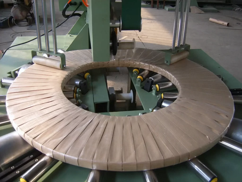
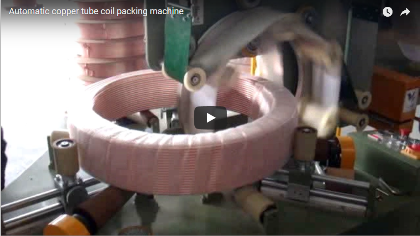
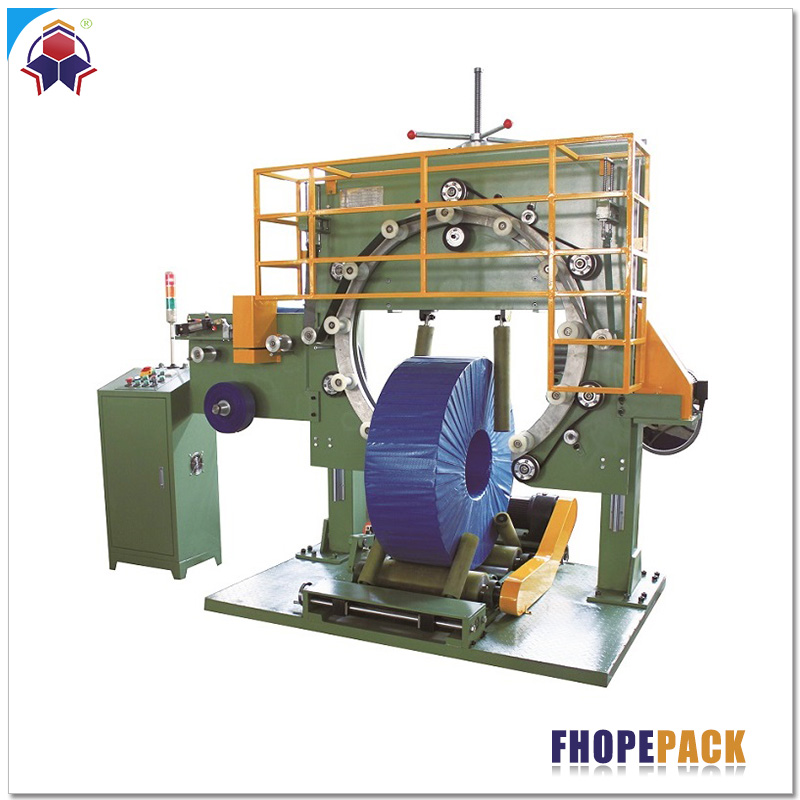
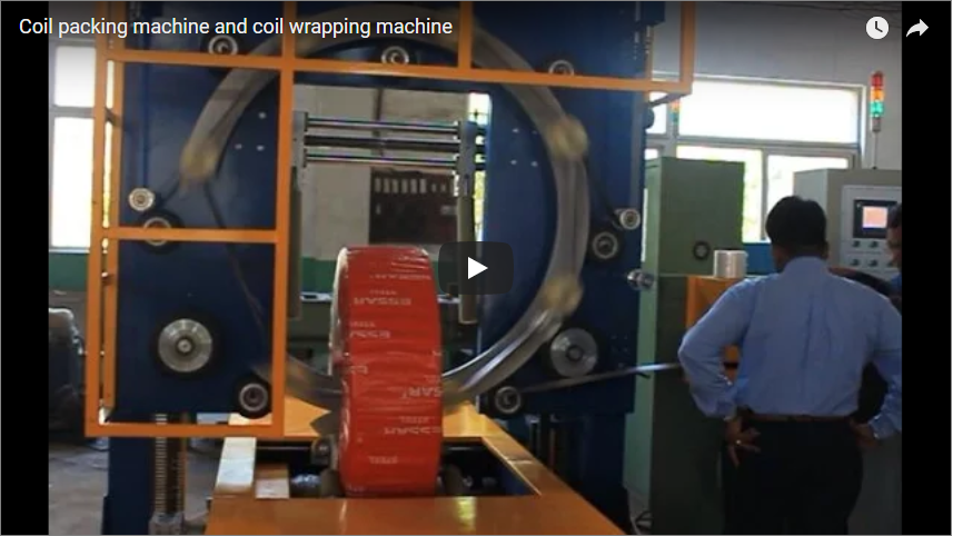
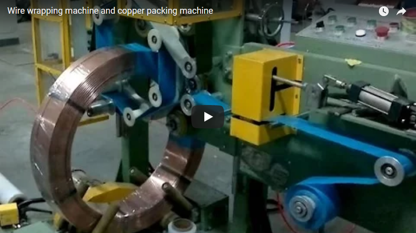
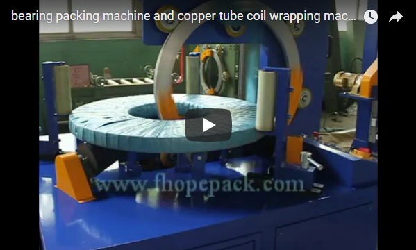
An eye-through copper strip coil wrapping machine applies stretch film, neutral crepe paper, or woven composite tape through the center bore and around the outer rim of a slit copper coil. Supported in an “eye-to-sky” (bore vertical) orientation on powered conveyor rollers, the coil rotates while an upright rotary ring continuously dispenses protective wrap through the bore. The heavy-duty FPC-300 accommodates coils from 10 to 1,000 kg with outer diameters (OD) of 700–1,200 mm, while the compact FPC-200 manages lighter coils of 5–500 kg (600–1,200 mm OD). The verified kinematic example below details layer overlap, film consumption, and cycle timing for an 84 kg slit copper coil.
Table of Contents
- Why copper strip coils need eye-through wrapping
- How the wrapper works
- Horizontal or vertical wrapping for copper strip
- FPC-300 and FPC-200 specifications
- Worked example: an 84 kg copper strip coil
- Selection checklist
- Safety: EN 415-10 and ISO 12100
- Engineering FAQ
- Next step
- Related reading
- Sources
Why copper strip coils need eye-through wrapping
Slit copper and brass strips (C11000, C26000) are highly susceptible to surface tarnishing, galvanic oxidation, and mechanical denting during transit. Ambient oxygen and moisture penetrating non-sealed packaging initiate rapid surface oxidation, creating uneven dark patches that ruin stamping and continuous electronic terminal punching lines. Furthermore, slit edges are soft and prone to burr deformation under point impact.
Standard radial stretch wrapping (covering only the outer circumference) leaves the inner bore and both side faces exposed. Eye-through orbital wrapping feeds packaging materials simultaneously through the internal bore, across both side faces, and over the outer diameter in one unified helical layer. This encapsulates the copper strip inside a hermetic, moisture-tight envelope while providing multi-layered impact padding along vulnerable slit edges.
How the wrapper works
The wrapping sequence follows a fully automated kinematic progression:
- Infeed & Positioning: The coil enters lying flat in an eye-to-sky pose on a polyurethane-coated powered roller conveyor. It stops precisely beneath the wrapping center line.
- Radial Clamping & Centering: Four adjustable upright guide rollers with pneumatic damping close in symmetrically against the coil outer diameter. These rollers center the coil and provide steady, slip-free rotational drive at a controlled surface speed.
- Orbital Wrap Application: An upright high-tensile cast-alloy ring carrying a pre-stretch film dispenser passes vertically through the open coil bore. As the coil slowly rotates on its horizontal plane, the ring revolves at high speed through the bore, wrapping material in a 360° toroidal pattern.
- Cutting & Discharge: Upon achieving programmed overlap layers, an integrated pneumatic clamp-and-cut unit secures and severs the film tail against the coil face. The centering rollers retract, and the powered conveyor transfers the packaged coil to downstream strapping or stacking stations without manual hoist intervention.
The operator monitors the entire sequence via an HMI touchscreen on a freestanding console positioned safely outside the perimeter guarding.
Horizontal or vertical wrapping for copper strip
Industrial coil wrapping machines fall into two main geometric configurations based on coil axis orientation:
- Eye-to-Sky (Horizontal Conveyor / Eye-Vertical) Wrapping: The coil lies completely flat on its face with its axis oriented vertically.
- Eye-Horizontal (Stand-on-Rim) Wrapping: The coil stands on its outer cylindrical perimeter with its core axis horizontal, supported on two drive cradles.
       Eye-to-Sky Orientation                  Eye-Horizontal Orientation
       (Recommended for Strip)                   (Wide/Master Coils Only)

         ┌───────────────────┐                         ╭─────────╮
         │  Slit Copper Coil │                         │  Coil   │
         └───────────────────┘                         │  Bore   │
       ═════════════════════════                       ╰─────────╯
        Flat Roller Conveyor Bed                     ▲ Drive Rollers ▲
     (Full support, zero edge load)              (Risk of edge bucking on thin strip)
Why Eye-to-Sky is mandatory for slit copper strip:
- Zero Edge Buckling: Slit copper coils often feature widths as narrow as 8–30 mm. Standing narrow strip coils on their rims exerts excessive concentrated weight on thin bottom edges, triggering severe edge mushrooming, lamination telescoping, or coil collapse.
- Continuous Face Support: Lying flat on the conveyor bed distributes coil self-weight evenly across the entire surface face, permitting soft-annealed strip of any width to run without mechanical distortion.
- Automated Transfer: Slit coils exiting the slitter turnstile are natively discharged flat, allowing direct transfer into an eye-to-sky wrapper without requiring expensive, high-risk 90° upending machines.
FPC-300 and FPC-200 specifications
| Technical Specification | FPC-200 (Light / Medium Duty) | FPC-300 (Heavy Duty Line) |
|---|---|---|
| Max. Coil Weight | 5–500 kg | 10–1,000 kg |
| Coil Width (Face Height) | 10–200 mm | 10–300 mm |
| Coil Outer Diameter (OD) | 600–1,200 mm | 700–1,200 mm |
| Coil Inner Diameter (ID) | 300–800 mm | 400–900 mm |
| Radial Wall Thickness ((OD − ID)/2) | ≤ 400 mm (OD − ID < 800 mm) | ≤ 300 mm (OD − ID < 600 mm) |
| Roller Conveyor Surface Speed | 2.0–4.0 m/min (Inverter controlled) | 2.0–4.0 m/min (Inverter controlled) |
| Wrapping Cycle Duration | 23–50 s / coil | 35–50 s / coil |
| Rotary Ring Drive Speed | 10–100 rpm (VFD smooth acceleration) | 5–100 rpm (VFD smooth acceleration) |
| Film Overlap Range | 20%–90% (Adjustable via HMI) | 10–90% (Adjustable via HMI) |
| Wrapping Material Compatibility | LLDPE Stretch Film, VCI Crepe Paper, Woven Tape | LLDPE Stretch Film, VCI Crepe Paper, Woven Tape |
| Material Roll Width / Core ID | 90–120 mm width / 50–76 mm core | 90–120 mm width / 50–76 mm core |
| Electrical / Pneumatic Rating | 380 V, 50/60 Hz, 3-Phase; 0.5–0.8 MPa air | 380 V, 50/60 Hz, 3-Phase; 0.5–0.8 MPa air |
Worked example: an 84 kg copper strip coil
Design Parameters:
- Material: Cold-rolled electrolytic copper strip (density ρ = 8,960 kg/m³)
- Dimensions: OD = 700 mm (0.7 m), ID = 500 mm (0.5 m), Width W = 50 mm (0.05 m)
- Packaging Specification: FPC-300 machine, film roll width = 100 mm, target overlap = 50%
| Engineering Check | Kinematic Calculation | Result & Compliance |
|---|---|---|
| 1. Total Coil Mass | M = (π / 4) × (OD² − ID²) × W × ρ = (π / 4) × (0.7² − 0.5²) × 0.05 × 8,960 | 84.45 kg (Compliant: 10–1,000 kg capacity) |
| 2. Radial Wall Thickness | T_wall = (OD − ID) / 2 = (700 − 500) / 2 | 100 mm (Compliant: well under 300 mm limit) |
| 3. Effective Film Step | S_step = Film Width × (1 − Overlap) = 100 mm × (1 − 0.50) | 50 mm / cycle |
| 4. Total Wraps Required | N_wraps = (π × OD) / S_step = (π × 700 mm) / 50 mm | 43.98 ≈ 44 ring revolutions |
| 5. Cross-Section Perimeter | P_sec = 2 × (T_wall + W) = 2 × (100 + 50) | 300 mm (0.30 m) |
| 6. Total Film Length | L_film = N_wraps × P_sec = 44 × 0.30 m | 13.2 m (excluding pre-stretch gain) |
| 7. Coil Rotation Duration | t_rot = (π × OD) / V_roller = (π × 0.7 m) / (3.0 m/min) × 60 s | 43.98 s ≈ 44 s (Fits within 35–50 s range) |
| 8. Required Ring Speed | ω_ring = (N_wraps / t_rot) × 60 s = (44 / 44 s) × 60 s | 60 rpm (Optimal within 5–100 rpm range) |
Engineering Analysis: At a conveyor speed of 3.0 m/min, the coil completes a 360° turn in 44 seconds. A ring speed of 60 rpm provides exactly 44 passes, achieving a uniform 50% overlap seal. If conveyor speed is boosted to maximum (4.0 m/min), coil rotation drops to 33 seconds, which falls below the FPC-300 minimum cycle clamp threshold (35 s) and requires ring acceleration beyond 80 rpm. Setting the roller drive inverter to 3.0 m/min maintains optimal mechanical balance and prevents stretch-induced edge shear.
Selection checklist
Before finalizing wrapping cell engineering specifications, verify the following boundary conditions:
- Dimensional Spectrum: Record maximum and minimum coil OD, ID, face width, and single-package gross weight.
- Corrosion Barrier Chemistry: Determine whether VCI anti-corrosion crepe paper must be cross-laminated under standard PE stretch film for overseas sea freight.
- Layer Overlap & Tension Setting: Define target overlap ratio (typically 50%–66%) and mechanical film tension limits (15–40 N) to avoid slit edge cut-through on soft copper alloys.
- Line Integration Degree: Specify whether loading requires a manual hoist with C-hook, automated push-feeders, or an inline powered chain/roller conveyor.
- Upstream Throughput Balance: Calculate total line yield in coils per hour (CPH) to prevent coil accumulation at the slitter discharge arm.
- Downstream Finishing Modules: Confirm integrated inline weighing scales, automatic radial ID/OD strapping systems, and robotic vacuum stackers.
Safety: EN 415-10 and ISO 12100
All packaging cells comply strictly with European Machinery Directives:
- ISO 12100:2010: Comprehensive risk mitigation covering mechanical pinch points around rotating rings and pneumatic roller carriages.
- EN 415-10: Specific safety standards for modular wrapping machines.
- Physical Isolation: Interlocked perimeter wire mesh fencing prevents operator entry during automatic high-speed ring rotation.
- Light Curtains & Category 4 E-Stop: Optical presence sensors at conveyor entry/exit points trigger dual-channel SIL 3 safety relays, halting the rotary ring within 0.6 seconds of light beam interruption.
Engineering FAQ
Q: Why wrap copper strip coils in an eye-to-sky (flat) orientation rather than on-edge? A: Laying the coil flat fully supports its face across heavy-duty urethane rollers. Narrow slit coils (under 50 mm wide) lack lateral rigidity; wrapping them on-edge causes strip telescoping and severe outer edge damage from handling and packaging tension.
Q: How does the wrapping film carriage pass through the closed coil bore? A: The coil centers over an open conveyor gap. An orbital rotary ring, positioned vertically, drives the carriage through the center bore and back outside the coil circumference. The coil rotates in place horizontally, allowing continuous spiral overlap without splitting the ring structure.
Q: Which wrapping medium best prevents surface oxidation on C11000 copper? A: A two-layer composite wrap provides superior results: an inner layer of neutral VCI (Volatile Corrosion Inhibitor) crepe paper that continuously emits vapor inhibitors, overlaid by a high-clarity LLDPE stretch film (20–25 µm) at 50% overlap to lock out moisture and ambient sulfur.
Q: Can the FPC-300 integrate directly into an automated slitting-packaging line? A: Yes. The system includes an industrial Siemens or Mitsubishi PLC with Profinet/Ethernet IP connectivity to link seamlessly with upender cars, turnstiles, and downstream automatic labeling and stacking conveyors.
Q: Which harmonized industrial safety standards govern machine design? A: Machine construction complies with EN 415-10 (Safety of packaging machines – modular and wrapping machines), with electrical systems built to EN 60204-1 and functional safety architected to ISO 13849-1 / ISO 12100.
Next step
- Submit Processing Data: Send your copper strip dimensional parameters (OD, ID, width, min/max weight, and line CPH target) to info@fhopepack.com.
- Review Layout Drawing: Receive an engineered 2D/3D plant layout matching your line height, material specifications, and conveyor footprint.
- Receive Formal Proposal: Our packaging team delivers an itemized engineering quote and line cycle-time simulation within 24 hours.
Related reading
- FPC-300 copper coil wrapper (product)
- FPC-200 copper coil wrapper (product)
- Steel coil and copper coil packaging machine for eye-through film wrapping
- Coil packing machine for copper and alloy steel strip
Sources
- FHOPE Technical Documentation: FPC-200 & FPC-300 Eye-Through Copper Coil Wrapping Systems
- Slit Strip Packaging Engineering Manual: Face Protection & Edge Integrity Guidelines
- International Standards: EN 415-10 (Packaging Machines Safety); ISO 12100:2010 (Risk Assessment); EN 60204-1 (Electrical Safety)
- Copper Development Association (CDA): Surface Oxidation & Passivation Guidelines for Wrought Strip Alloys
Last reviewed: 2026-10-19