Executive summary
Certain high-value cartons, profiles, and industrial bundles require a branded, puncture-resistant outer barrier rather than thin stretch film. Our BOPP tape orbital wrapping machine continuously applies printed or plain polypropylene adhesive tape in a spiral helix around long products as they pass through a motorized rotating ring. Equipped with synchronized pneumatic top/side press units, mechanical tape tension regulation, and an automatic clamp-and-cut station, the system provides customizable pitch overlap from 10% to 90%. This guide details the structural layout, overlap kinematics, tape consumption formulas, and technical selection criteria.
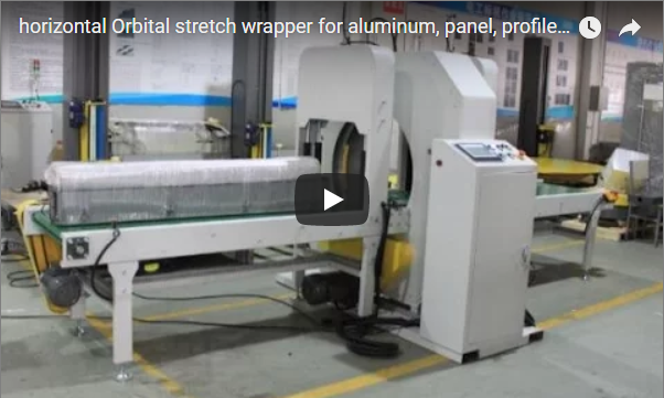
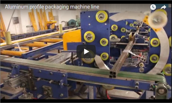
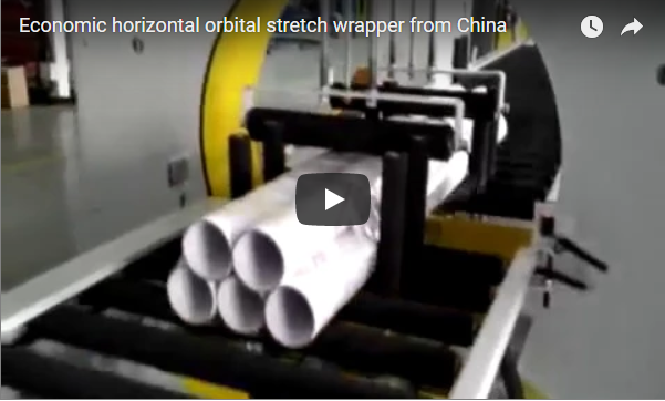
The orbital tape wrapper integrates a high-rigidity structural frame, a precision cast-aluminum rotor ring supported by heavy-duty polyurethane guide wheels, and vulcanized rubber roller conveyors. Engineered for automated packing lines, pneumatic vertical hold-down assemblies and dual lateral guide rollers secure cartons and profile bundles against centrifugal displacement during high-speed spiral taping.
Table of Contents
- Why BOPP Tape Instead of Film
- How the Machine Works
- Machine Build & Specifications
- Overlap Kinematics and Tape Consumption
- Engineering Selection Checklist
- Industrial Safety Standards
- Engineering FAQ
- Next Step
- Related Reading
- Sources
Why BOPP Tape Instead of Film
Biaxially Oriented Polypropylene (BOPP) tape exhibits significantly higher tensile modulus and lower elongation than standard LLDPE stretch film. While stretch film relies on elastic memory and surface cling to contain loose items, BOPP packaging tape provides rigid edge sealing, aggressive shear resistance, and permanent branding in a single continuous pass.
- Branding and Tamper Evidence: Custom-printed BOPP tape displays logos, barcode data, and tamper-indicating graphics along the entire package length, eliminating secondary labeling.
- Structural Bundle Rigidity: The non-elastic properties of BOPP prevent longitudinal slippage in bundled pipes, extrusions, and telescoping boxes.
- Scuff and Abrasion Protection: BOPP film backing resists gouging and punctures during intermodal transit far better than unbonded polyethylene wraps.
- Single-Pass Enclosure: Spiral taping seals flap seams while simultaneously bundling, removing the need for dedicated top-and-bottom case sealers.
How the Machine Works
The automated cycle coordinates synchronized conveyor travel with ring rotation via industrial PLC tracking:
- Infeed & Detection: The product enters the conveyor bed; a diffuse optical photocell detects the leading edge and indexes the package into the wrapping plane.
- Pneumatic Stabilization: Overhead press-down rollers and lateral guide assemblies lower onto the product with regulated pneumatic pressure (0.2–0.4 MPa) to counteract tape wrapping torque.
- Tape Clamp & Lead-In: An automatic pneumatic clamp holds the tape leader against the workpiece entry face to initiate adherence without operator intervention.
- Orbital Spiral Wrapping: The cast ring accelerates smoothly via Variable Frequency Drive (VFD). As the product advances longitudinally, the ring spirals tape around the circumference. Programmable logic executes preset reinforcement wraps (1 to 5 turns) at the front and tail ends.
- Wipe-Down & Cut-Off: At the trailing edge, a pneumatic clamping arm grips the tape tail, an anti-adhesive cold blade executes a clean cross-cut, and a trailing wipe-down brush or roller presses the tape end securely against the carton surface.
- Outfeed: The finished, bundled package transfers to the downstream exit roller table.
Machine Build & Specifications
Standard engineering specifications for the automatic tape orbital packaging platform:
| Functional Module | Engineering Design Parameters |
|---|---|
| Rotor Ring Assembly | Solid cast aluminum alloy ring, dynamic-balanced; mounted on 4 precision alloy guide wheels with dual PU friction drive wheels |
| Drive Transmission | Inverter-controlled 1.5–2.2 kW AC gear motor; variable acceleration/deceleration S-ramps; jog positioning |
| Tension Control | Adjustable mechanical friction brake / magnetic powder tensioner maintaining 5–25 N tape payout tension |
| Overlap Range | 10% to 90%, steplessly regulated via PLC-linked conveyor/ring speed ratios |
| Conveyor System | Heavy-duty vulcanized rubber rollers (Shore A 65) or PVC belt conveyors; motorized VFD synchronization; 1.5–3.0 m infeed/outfeed sections |
| Cut & Clamp Unit | Pneumatic cylinder clamp with PTFE-coated anti-stick knife blade and flexible wipe-down pressure pad |
| Automation & Interface | Siemens / Delta PLC; color HMI touchscreen; integrated optical sensors for cycle sequencing |
| Floor Loading Requirement | Reinforced concrete industrial floor, rated load capacity ≥1.0 t/m² |
Note: Ring internal diameter, maximum cross-sectional passage (W × H), and conveyor payload capacity are tailored to product envelope specifications during engineering review.
Overlap Kinematics and Tape Consumption
Achieving a uniform seal without wasting material requires precise synchronization between the linear conveyor velocity and ring rotational speed.
Conveyor Speed (m/min) = Ring Speed (rpm) × Tape Width (m) × (1 − Overlap Ratio)Where:
- Tape Width is expressed in meters (e.g., 72 mm = 0.072 m).
- Overlap Ratio is expressed as a decimal (e.g., 50% overlap = 0.50).
To estimate tape roll consumption per wrapped bundle:
Total Tape Length (m) ≈ [Pack Perimeter (m) × Pack Length (m) ÷ (Tape Width (m) × (1 − Overlap Ratio))] + (Reinforcement Wraps × Pack Perimeter)Engineering Calculation Example
- Pack Cross-Section: 0.3 m (W) × 0.3 m (H) (Perimeter = 2 × (0.3 + 0.3) = 1.2 m)
- Pack Length: 2.0 m
- Tape Width: 0.072 m (72 mm)
- Overlap: 50% (0.50)
- Reinforcement Wraps: 2 wraps at entry + 2 wraps at exit = 4 wraps total
Body Spiral Tape = 1.2 × 2.0 ÷ (0.072 × 0.50) = 2.4 ÷ 0.036 ≈ 66.7 m
Reinforcement Tape = 4 × 1.2 = 4.8 m
Total Tape per Pack ≈ 66.7 + 4.8 ≈ 71.5 m
Note: For edge-sealing integrity, a minimum overlap of 25% is recommended to prevent separation along bundle corners.
Engineering Selection Checklist
To obtain an accurate configuration and layout drawing, verify the following boundary parameters:
- Product Dimensions: Minimum and maximum bundle dimensions: Length (L) × Width (W) × Height (H) in millimeters.
- Cross-Sectional Diagonal: Calculate
D_max = √(W² + H²). Ensure the ring inner diameter provides at least 150–200 mm clearance aroundD_maxto clear the rotating tape dispenser carriage. - Tape Specifications: Tape roll backing (BOPP/PVC), adhesive chemistry (water-based acrylic / hot melt), film thickness (µm), roll outer diameter, and core diameter (usually 76 mm / 3 in).
- Target Cycle Rate: Required line throughput (bundles per hour or meters per minute).
- Upstream/Downstream Integration: Standalone operation with manual infeed, or continuous tie-in with an automated production line via dry contacts or Ethernet/IP.
Industrial Safety Standards
FHOPE orbital packaging machinery complies with international industrial safety and machinery directives:
- EN ISO 12100:2010: Risk assessment and risk reduction methodology integrated into all moving mechanical linkages.
- EN 415-10: General safety requirements for packaging machines and orbital wrapper integration.
- EN 60204-1: Electrical safety of machinery, including continuous grounding, emergency stop circuits (Category 0/1), and 24 V DC control voltages.
- Safety Hardware: Full-perimeter expanded metal mesh guards enclose the spinning ring zone; dual safety interlock switches halt ring rotation immediately upon guard door opening.
Engineering FAQ
Q: Can this machine handle both BOPP adhesive tape and standard stretch film? A: Yes, provided the optional dual-carriage bracket is installed. However, because BOPP tape operates under zero-elongation conditions while stretch film requires dynamic pre-stretch tension, the operator must switch the operating profile on the HMI and swap the dispensing core mechanism.
Q: Will the pneumatic clamps and roller guides mar sensitive cartons or high-gloss surfaces? A: No. All clamping plates, side guide rollers, and vertical press-down wheels are jacketed in high-resilience non-marking polyurethane or soft synthetic rubber (Shore A 45–60). Air pressure is regulated via precision air filters with safety check valves.
Q: How does the cutting mechanism prevent adhesive gumming on the blade? A: The cut-off unit utilizes a high-carbon tool steel blade treated with a specialized PTFE fluoropolymer coating. This prevents the pressure-sensitive adhesive from accumulating on the cutting face, eliminating skipped cuts during high-volume shifts.
Q: Can reinforcement wraps be adjusted independently for the front and tail ends? A: Yes. The HMI allows discrete integer settings (0–9 turns) for both the leading edge and trailing edge reinforcement cycles, as well as intermediate dwell positions.
Next Step
- Submit Product Parameters: Forward your pack dimension matrix (L × W × H), weight range, and required throughput to info@fhopepack.com.
- Layout & Ring Sizing: Our engineering department generates ring clearance diagrams and conveyor layout drawings within 24 hours.
- Comprehensive Proposal: Receive a complete technical specification package, cycle-time simulation, and commercial quotation.
Related Reading
- Profile Orbital Wrapping Machine (Product Specification)
- Panel Wrapping Machine and Board Bundling Lines (Product)
- Economic Orbital Wrapper Video Demonstration
- Rod & Bar Orbital Wrapping Machinery (Video Case Study)
- Horizontal Orbital Stretch Wrapping Solutions
Sources
- FHOPE Technical Design Data: E-Series Orbital Wrapping Systems
- European Standard EN ISO 12100:2010 (Safety of Machinery – General Principles for Design)
- European Standard EN 415-10 (Safety of Packaging Machines – Modular Formats)
- European Standard EN 60204-1 (Safety of Machinery – Electrical Equipment of Machines)
Last reviewed: 2026-10-20