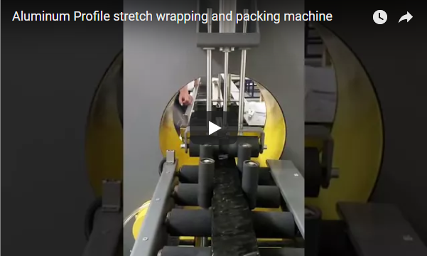
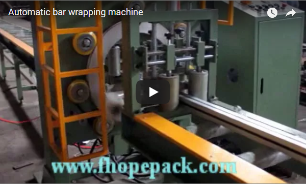
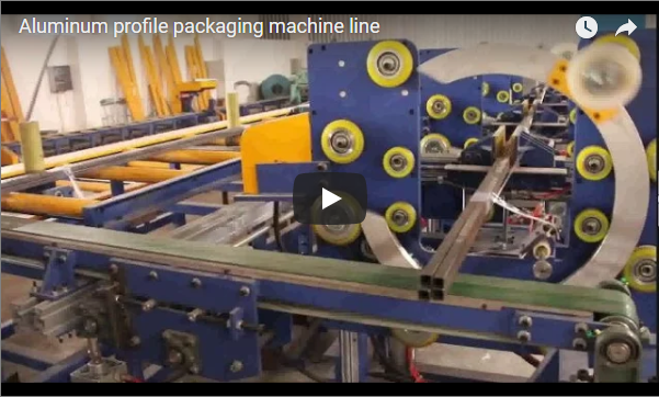
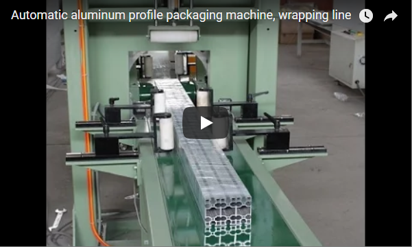
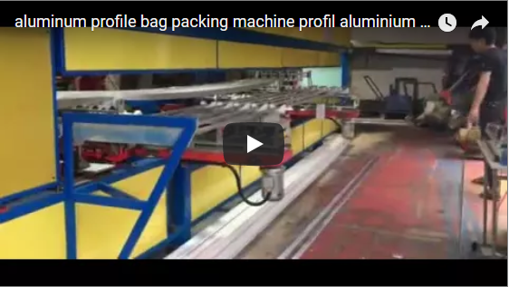
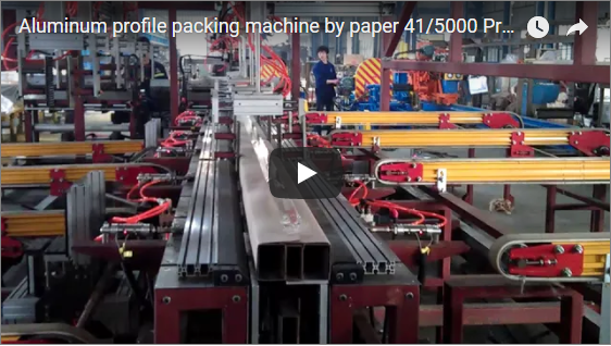
Executive summary A protective film application machine presses a self-adhesive film onto the face of a flat sheet as the sheet passes between rollers. Our machine does this in one pass on a roller conveyor, so each sheet leaves with its face covered and ready to stack. The film width follows from the sheet width, and the roll yield from the sheet length. Both are set per project to your sheet.
Table of Contents
- What the machine does
- How sheet film application works
- Sizing the film width
- Working out roll yield
- Controls and safety
- Selection checklist for a sheet film applicator
- Engineering FAQ
- Next step
- Related reading
- Sources
What the machine does
An automatic protective film application machine applies surface protection to flat sheets in a single, continuous in-line pass. The flat product enters the infeed roller conveyor horizontally, where an overhead film unwind station dispenses protective film in line with the conveyor travel.
As the sheet advances through a motorized nip assembly, rubber-lined rollers press the self-adhesive film evenly against the top surface. The film bonds continuously from the leading edge to the trailing edge without manual intervention. The covered sheet then discharges fully covered, flat, and ready for stacking or packaging.
How sheet film application works
The mechanical cycle operates through five synchronized stages:
| Step | What happens |
|---|---|
| Infeed | The sheet is laid flat on the infeed and carried forward |
| Film feed | Film unwinds from the roll above the sheet |
| Nip | A pair of rollers presses the film onto the sheet face |
| Separation | The film is parted between one sheet and the next |
| Discharge | The covered sheet leaves on the outfeed |
The mechanical pressure at the nip is what activates the pressure-sensitive adhesive and makes the film bond evenly. Too little pressure leaves air bubbles, and too much can mark a soft surface. Roller force and web tension are adjusted by trial on your sheet and film.
In conventional manual setups, surface protection and trimming typically require a two-person crew: one operator feeding and aligning the product, and a second handling tension and cutting. Automated sheet film application replaces those manual tasks and saves one operator per line [manufacturer rating, applicator-equipment baseline].
Sizing the film width
The film is usually selected slightly wider than the sheet so the outer edges receive full protective coverage against handling abrasions, leaving an overhang that can be trimmed or folded along downstream processes. Below is an illustrative engineering example for a standard 1,220 mm wide sheet with a 10 mm edge allowance allocated to each side:
| Item | Value |
|---|---|
| Sheet width | 1,220 mm |
| Edge allowance, 2 × 10 mm | 20 mm |
| Film width, 1,220 + 20 | 1,240 mm |
Some production environments prefer a roll width slightly narrower than the sheet, so no adhesive overhang reaches the edge and no secondary trimming is needed. Tell us which you need when you send your sheet sizes.
Working out roll yield
Because film dispenses along the axis of travel, each sheet consumes a roll length equal to its overall longitudinal dimension plus cut clearance. Below is an illustrative yield projection for 2,440 mm long sheets processed from a standard 500 m continuous supply roll:
| Item | Value |
|---|---|
| Sheet length | 2,440 mm |
| Roll length (illustrative) | 500 m |
| Sheets per roll, 500 ÷ 2.44 | about 204 |
| Film per sheet, 1.24 m × 2.44 m | about 3.0 m² |
A longer roll means fewer roll changes per shift. Count the roll-change time when you plan output.
Controls and safety
The primary mechanical hazard on any roller-fed laminator is the nip point: the counter-rotating infeed between the upper pressure roller and the lower conveyor roller can draw in fingers, gloves, or loose clothing along with the incoming sheet.
Operators must keep hands outside designated light curtain or physical guard boundaries while the conveyor drives are energized. The machine must be stopped and isolated under Lockout/Tagout (LOTO) protocols prior to clearing sheet jams, setting mechanical nip stops, or threading a new master roll through the tensioning dancers.
Applicable functional safety and construction requirements depend on the destination facility. For European CE markets, machinery design complies with ISO 12100 for comprehensive risk-assessment principles and EN 415-10 for packaging machine mechanical safety, interlocking guard perimeters, and emergency stop circuits.
Selection checklist for a sheet film applicator
- Sheet width, length and thickness, smallest to largest.
- Sheet material and surface finish.
- Film on one face or both faces.
- Film type and roll size you use now.
- Sheets per hour.
- How sheets reach the infeed and leave the outfeed.
Engineering FAQ
Q: What sheets suit this machine? A: Flat sheets that can lie on the conveyor, such as plastic, composite or metal sheet.
Q: How wide should the film be? A: Standard practice selects a roll width matching the sheet width plus a dedicated edge allowance. Our standard 1,220 mm sheet example utilizes a 1,240 mm master roll, providing a 10 mm continuous overlap on either side.
Q: How many sheets does a roll cover? A: Total coverage equals nominal roll length divided by cut length per sheet. Our 500 m illustrative roll yields approximately 204 sheets of 2,440 mm length. On specialized automated equipment, continuous roll stock is metered against product sensors, and servo systems pre-cut film segments directly to measured workpiece length [manufacturer rating, equipment-level baseline].
Q: Why do air bubbles appear? A: Bubbles generally stem from inadequate pneumatic nip downward force or unbalanced unwind brake tension. When web tension fluctuates across the roller face, the film wrinkles prior to contact, trapping air pockets. Correct this by calibrating linear roller pressure and setting unwinding brake friction to match your specific film backing.
Q: Can it cover both faces? A: Yes. A second film roll can be added for the lower face. Tell us if you need it.
Next step
We plan your sheet film applicator in three steps:
- Submit your layout drawing with sheet sizes and output to info@fhopepack.com.
- Receive a proposal within 48 hours, with the film width and roll plan.
- Book a site survey to check the infeed and outfeed layout.
Related reading
- Video: protective foil application machine on sheet
- Video: automatic cutting of film covering machine on sheets
- Automatic strapping machines
Sources
- Machine content: FHOPE engineering team, 2026-10-04
- Film width and roll yield: our worked examples, illustrative values
- Machine in action: our video on YouTube
- Standards scope: ISO 12100:2010, EN 415-10:2014
- Automated surface protection reference: Automatic aluminum profile protective film applicator (profile applicator equipment baseline)
Last reviewed: 2026-10-29