Executive summary
Large ring-shaped and rectangular workpieces have to change between vertical and horizontal, and the flip is wasted if the next step still has to move the load. This hydraulic-style upender pairs a roller clamp with a sliding table: it flips the load, moves the flipped load onto a roller conveyor, and returns for the next cycle. We build upenders with pallet positioning and sliding tables. Load range and cycle plan are confirmed per project.
Table of Contents
- Why the flip is not the whole step
- What the machine does
- Flipping the workpiece
- The roller clamp
- The sliding table handoff
- Returning for the next cycle
- Typical configuration
- What the video shows
- Selection checklist
- Operation and safety
- Engineering FAQ
- Next step
- Related reading
- Sources and standards
Why the flip is not the whole step
Flipping a large workpiece earns nothing if the flipped load then has to be removed by hand, because the risk and the labor come back. The useful operation ends when the load is on the next conveyor, in the right orientation. The machine therefore pairs the flip with the handoff that completes it. The load range and its flow are confirmed per project.
What the machine does
The upender flips large workpieces between vertical and horizontal and moves the flipped load onto a roller conveyor, all in one controlled cycle. A roller clamp holds the load during rotation, a sliding table carries the flipped load across, and the table returns for the next piece. Because the flip and the handoff are joined, the load leaves as the step completes. The covered cycle is confirmed per project.
Flipping the workpiece
The machine rotates the workpiece between vertical and horizontal on hydraulic-style action, turning large ring-shaped and rectangular parts cleanly. The flip is done under control, with the load supported through the whole motion. A controlled flip is what protects the workpiece from the marks and damage of a loose turn. The flip travel follows the workpiece geometry, confirmed per project.
The roller clamp
A roller clamp holds the load during rotation, securing the workpiece so it cannot shift as it turns. The clamp grips along rolling elements that hold without scoring the workpiece surface. Holding the load firmly is what makes the flip predictable. The clamp and its setup follow the workpiece shape, confirmed per project.
The sliding table handoff
A sliding table moves the flipped load onto the roller conveyor, completing the orientation where the next process takes it. The handoff is the part that removes the crew from between the machines. With the load delivered onto the conveyor, the flip has produced the actual step. The table travel and conveyor interface are confirmed per project.
Returning for the next cycle
After delivering the load, the table returns automatically for the next cycle, keeping the machine ready before the next piece arrives. Automatic return is what lets the upender run at the line’s rhythm instead of waiting between loads. The machine is always back in position when the next workpiece comes. The cycle rhythm is confirmed per project.
Typical configuration
Figures below list functional design boundaries rather than numeric values, and are confirmed per project.
| Parameter | Typical range, confirmed per project |
|---|---|
| Workpiece | rings, rectangles |
| Clamp | roller hold |
| Flip | hydraulic-style |
| Table | sliding handoff |
| Cycle | return |
| Electrical supply | 380 V three phase 50 Hz, or 220 V single phase for light machines, selected per project |
What the video shows
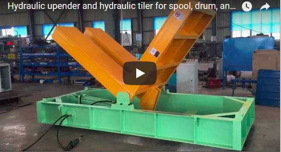
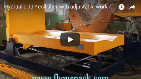
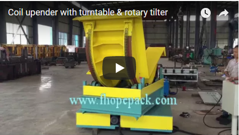
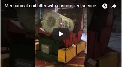
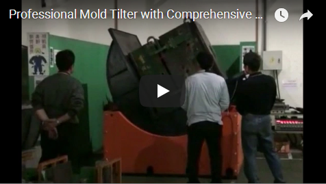
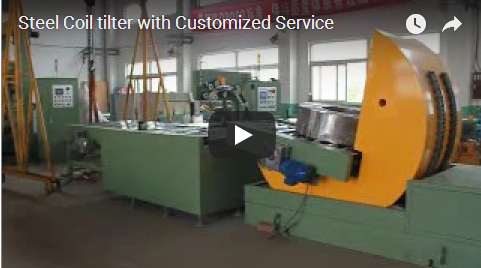
Our footage shows an upender flipping large workpieces and handing them to a roller conveyor. It is a general demonstration, so your load range and cycle plan are confirmed with us per project.
Selection checklist
| Question | Confirm per project |
|---|---|
| Workpiece | sizes, shapes |
| Clamp | roller hold |
| Flip | travel |
| Table | handoff |
| Cycle | rhythm |
| Electrical supply | voltage, phase and frequency on site |
Operation and safety
Run the cycle from the panel and the machine clamps, flips and hands off each load automatically. Keep clear of the clamp, flip path, sliding table and conveyor while the machine runs, with guarding and emergency stops at the operator position. Routine checks cover the clamp, drive, table, sensors and control, per the machine manual. Confirm the cycle against the workpiece before each run so loads flip and hand off cleanly.
Engineering FAQ
Q: What does this upender do? A: It flips large workpieces and moves them onto a roller conveyor in one cycle.
Q: Why the roller clamp? A: It holds the load during rotation without scoring the workpiece.
Q: What does the sliding table add? A: It delivers the flipped load to the conveyor, completing the step.
Q: Why return automatically? A: So the machine is ready before the next workpiece arrives.
Q: What does it flip? A: Large ring-shaped and rectangular workpieces, confirmed per project.
Next step
- Email us at info@fhopepack.com with your load range and flow.
- We send an upender proposal and a layout drawing within 48 hours.
- We arrange a site survey to confirm load range and conveyor interface.
Related reading
- Steel sheet inverter and upender
- 180° Upender: Operation and Applications
- C shape pallet inverter
- FHOPE packing machinery product lines
Sources and standards
- ISO 12100:2010 Safety of machinery, general principles for design and risk assessment
- EN 415-10:2014 Safety of packaging machines, general requirements
- EN ISO 13849-1:2023 Safety of machinery, safety-related parts of control systems
FHOPE upender with pallet positioning and sliding table demonstration video. Reviewed as a general demonstration based on the footage; load range confirmed per project.
Last reviewed: 2026-10-10