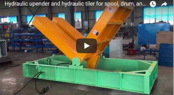
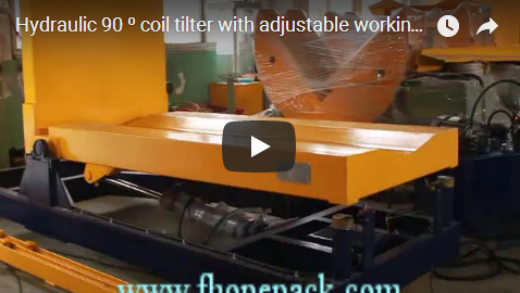
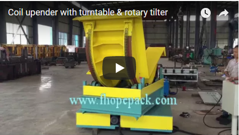
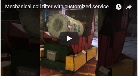
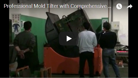
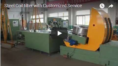
Executive summary A tilter and upender with a rotation table turns a heavy load such as a coil or a mould through 90 degrees, from lying to standing or back. Our clip, about 144 s long, shows two yellow cradle tilters on blue bases; the left one runs through two full tilt cycles empty. Our rotating upender handles 2,000 kg to 40 t at 60 to 90 s per turn.
Table of Contents
- What the clip shows, in order
- Cycle time on the clip
- How a cradle tilter works
- Rotating upender specifications
- Takt check
- Selection checklist for a tilter and upender
- Controls and safety
- Engineering FAQ
- Next step
- Related reading
- Sources
What the clip shows, in order
Each tilter has a yellow L-shaped table on a large curved cradle, mounted on a blue steel base. The edges of the table carry black and yellow hazard stripes. Black hoses run from the base, and a white box stands at the lower right. No load and no person are in the frames.
- 0 to about 12 s. Both tilters stand at rest, side by side. The left one has its table arms open at an angle.
- About 16 to 28 s. The left tilter turns. The cradle rolls and the L-table swings through about 90 degrees in one smooth move.
- About 32 to 44 s. The left tilter holds the turned position.
- About 48 to 56 s. It turns back to its start position. The right tilter stays still throughout.
- About 60 to 68 s. Both tilters are in the low position.
- About 72 to 96 s. The left tilter turns up again from about 72 to 88 s, then holds at the top until about 96 s, with the front face fully swung up.
- About 100 to 116 s. It swings back down and comes to rest in the low position.
- About 120 to 144 s. After a pause, the table starts another turn.
Cycle time on the clip
| Step on the clip | Time window | Duration |
|---|---|---|
| First turn up | about 16 to 28 s | about 12 s |
| Hold at the top | about 32 to 44 s | about 12 s |
| Turn back | about 48 to 56 s | about 8 s |
| Second turn up | about 72 to 88 s | about 16 s |
| Second turn back | about 100 to 116 s | about 16 s |
The times come from frames 4 s apart, with the machine empty. Our quoted 60 to 90 s per piece covers a loaded cycle, including load settling and the slower speed under load.
How a cradle tilter works
The load sits in the corner of the L-shaped table. The table is fixed to a curved cradle that rolls on support rollers in the base. As the drive turns the cradle, the L-table swings through 90 degrees. The floor face becomes the side face, and a lying load ends up standing. The rotation here is this 90 degree roll of the cradle, not a turntable spin.
The load rests on two faces of the table during the whole turn, so it is supported both before and after it changes position. The drive brake holds the table at any point of the turn.
| Part | What it does |
|---|---|
| L-shaped table | Carries the load on its base and back faces |
| Curved cradle | Rolls on the base and turns the table through 90 degrees |
| Blue base with support rollers | Carries the cradle and the load |
| Drive and brake | Turns the cradle and holds it in any position |
| Hazard stripes on the table edges | Mark the moving edges |
Our rotating upender comes with a flat table or a V table, both 1,500 by 1,500 mm, sized to the load.
Rotating upender specifications
| Rotating coil upender | Specification |
|---|---|
| Maximum load | 2,000 kg to 40 t |
| Products | Steel coils, moulds and similar loads |
| Flat table size | 1,500 × 1,500 mm, customised |
| V table size | 1,500 × 1,500 mm, customised |
| Turn time | 60 to 90 s per piece |
| Up-ending angle | 90 degrees |
| Power supply | 380 V, 50 Hz, 3 phase |
| Power | about 4.0, 5.0 or 15 kW by size |
Takt check
For an illustrative target of 30 loads per hour, the takt is 3,600 ÷ 30 = 120 s per load. A quoted 60 to 90 s per piece leaves 30 to 60 s to place the load and take it off by crane or forklift.
At the slow end that is tight for crane handling. Where the load comes on a conveyor, we add powered rollers on both table faces, so the load runs in and out without a crane hook.
Selection checklist for a tilter and upender
- Load type, weight and size, against 2,000 kg to 40 t.
- Flat table or V table for the load shape.
- Turn direction: lying to standing, standing to lying, or both.
- Loading by crane, forklift or conveyor.
- Loads per hour against the 60 to 90 s turn time.
Controls and safety
The cradle and the L-table move a heavy load through a wide arc, and the gap between the cradle and the base closes as it turns. On the clip nobody stands near the tilters while they move, and that is how we lay out the cell. A person inside the arc of the table is the move to design out.
The drive brake holds the table in any position. Stop, isolate and lock out the tilter, with the table at rest in a low position, before anyone enters the cradle area or works on the drive. Loads are placed and removed only with the table stopped at rest.
The standards that apply depend on the destination market. For CE markets, EN 415-10 covers general requirements for packaging machines, which fixes guarding and the stop arrangement, and ISO 12100 sets the risk-assessment method.
Engineering FAQ
Q: How heavy a load can the rotating upender turn? A: From 2,000 kg up to 40 t, depending on the size.
Q: How long does one 90 degree turn take? A: Our upender is quoted at 60 to 90 s per piece under load. The empty turn on the clip takes about 12 to 16 s.
Q: Which table types are available? A: A flat table or a V table, each 1,500 by 1,500 mm as standard and customised to the load.
Next step
We size a tilter and upender in three steps:
- Submit your layout drawing with the load type, weight, size and handling method, to info@fhopepack.com.
- Receive a proposal within 48 hours, with the table type, the drive size and the cycle check.
- Book a site survey so we confirm the floor, the crane reach and the safe zone around the tilter.
Related reading
- Rotating coil upender
- Upender and tilter with sliding table
- Coil upenders
- Coil tilter and upender: 90° turn of a palletised coil
Sources
- Machine specifications: rotating coil upender product page
- Clip timing: frame timings taken from our clip, 4 s between frames
- Machine in action: our video on YouTube
- Standards scope: EN 415-10:2014, ISO 12100:2010
Last reviewed: 2026-10-05