Executive summary
Long pipe leaves the line coiled, cut and strapped in one automatic pass. An automatic pipe coiling strapping machine measures the pipe as it feeds, winds it in even layers onto a coil, cuts it at the target length and straps the coil so it holds together through handling. This guide covers the coiling geometries, the cut and the strap cycle. Pipe sizes and strap pattern are confirmed per project.
Table of Contents
- What the machine does
- Two coiling geometries
- Measured and synchronized
- Neat, even coils
- Cut at the target
- Strapping the coil
- Typical configuration
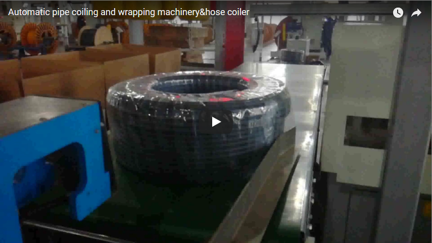
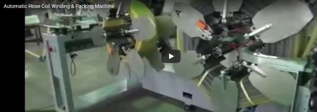
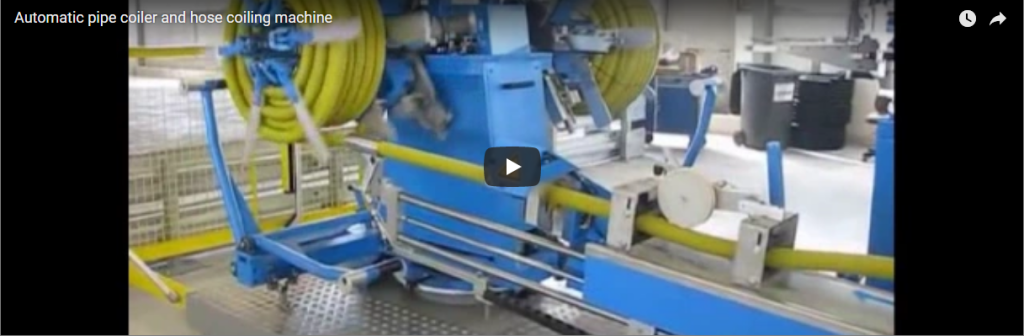
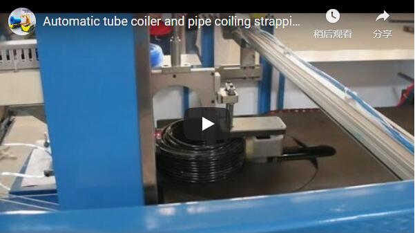
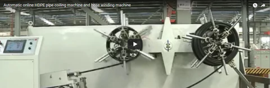
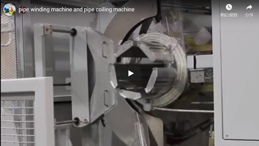
- What the video shows
- Selection checklist
- Controls and safety
- Engineering FAQ
- Next step
- Related reading
- Sources and standards
What the machine does
An automatic pipe coiling strapping machine takes extruded pipe or hose and turns it into a packaged coil in one workflow. The pipe feeds in and is measured, a coiling unit winds it into a neat coil, a cutter severs it at the preset length, and a strapping unit secures the finished coil. Manual coiling is slow and drifts between operators; this sequence takes the coil’s size and tightness off the operator’s hands and puts them on the line.
Two coiling geometries
The coiling unit uses one of two arrangements. With a rotating arm or flyer, the pipe stays relatively stationary while a winding arm orbits it, guiding the product onto a forming drum or directly into a coiling basket. With a rotating coiling head, the pipe feeds onto a head or drum that rotates and winds the material. Both give a formed coil; the choice follows the pipe range and the upstream line, and is confirmed per project.
Measured and synchronized
Coiling quality starts with feed control. We track the product length as it feeds, so the coil winds to the length the product calls for rather than the operator’s estimate. We match coiling speed to the upstream extrusion or feed line, and dancers or sensors feed back so the product is neither stretched nor left sagging between operations.
Neat, even coils
The coil’s shape comes from the head and the traverse. The winding head sets the inner diameter, and a traversing guide lays the pipe side by side in even layers to control the coil width. Inner diameter, outer dimension and width are set at a control interface, typically a touchscreen, and recalled per product. Even layers are what keep a finished coil from slumping on its pallet.
Cut at the target
When the preset length is wound, an integrated cutter severs the pipe cleanly. Because the cut follows the measured feed, every coil leaves the head at the same point, which keeps coil size and weight consistent across the run.
Strapping the coil
Immediately after coiling, the strapping unit secures the coil so it does not unwind during handling, storage or transport. PP and PET straps are the common choices: PET suits rigid, settling coils that need retained tension, and PP suits lighter standard coils for cost. Width, thickness and pattern follow the coil weight and handling duty, per project.
The strapping head tensions, seals and cuts the strap, and an indexing mechanism can rotate the coil between several strap positions around its circumference for better stability.
Sensors confirm the coil’s presence and position before each strap is applied, and they flag a missed strap or a strap jam before the coil leaves the station.
Typical configuration
Figures below list functional design boundaries rather than numeric values, and are confirmed per project.
| Parameter | Typical range, confirmed per project |
|---|---|
| Pipe or hose range | infeed and mandrel envelope |
| Coiling | rotating arm or coiling head |
| Coil plan | inner diameter, width, layers |
| Cut | at measured target length |
| Strapping | PP or PET, index positions |
| Control | PLC with touchscreen recipes |
| Electrical supply | 380 V three phase 50 Hz, or 220 V single phase for light machines, selected per project |
What the video shows
Our footage shows a pipe being coiled, cut and strapped on one machine. It is a general demonstration, so pipe range, coil plan and strap pattern for your plant are confirmed with us per project.
Selection checklist
| Question | Confirm per project |
|---|---|
| Pipe range | infeed, head and traverse envelope |
| Coil plan | inner diameter, width, layers |
| Feed sync | upstream line speed and feedback |
| Strapping | PP or PET, index positions |
| Output | machine cycle fit |
| Electrical supply | voltage, phase and frequency on site |
Controls and safety
The machine runs from a PLC control panel with a touchscreen, an emergency stop at the operator position and guarding around the winding head, cutter and strap zone. Keep hands clear while the cycle runs. Routine checks cover the measuring device, coiling head, traverse, cutter, strapping head and sensors, per the machine manual.
Engineering FAQ
Q: What sets the coil size? A: Three integrated parameters: the winding head sets the inner diameter, the traverse sets width in layers, and the measured feed sets the cut length, all from the panel plan.
Q: Which coiling arrangement should we pick? A: Rotating arm suits a relatively stationary pipe wound onto a forming drum, and a coiling head feeds the pipe onto the rotating unit; the choice follows your pipe range and line, per project.
Q: How is coiling matched to the extruder? A: Feed and coiling speed are synchronized, with dancers or sensors feeding back so the product is not stretched or sagging.
Q: Why strap right after coiling? A: Strap applied on the same machine holds the coil together before handling, with several positions indexed around the circumference per plan.
Q: What products run through it? A: Extruded pipe, tube or hose that suits automatic coiling, with the range confirmed per project.
Next step
- Email us at info@fhopepack.com with your pipe range, coil plan and volumes.
- We send a coiling-and-strapping proposal and a layout drawing within 48 hours.
- We arrange a site survey to confirm services and floor space.
Related reading
- Automatic coiler for hose and pipe with wrapping machine
- Automatic hose coil making machine: technology and best practices
- Automatic wire coiler and strapping machine
- FHOPE packing machinery product lines
Sources and standards
- ISO 12100:2010 Safety of machinery, general principles for design and risk assessment
- EN 415-10:2014 Safety of packaging machines, general requirements
- EN ISO 13849-1:2023 Safety of machinery, safety-related parts of control systems
FHOPE automatic pipe coiling strapping machine demonstration video. Reviewed as a general demonstration; pipe range, coil plan and strap pattern confirmed per project.
Last reviewed: 2026-10-10