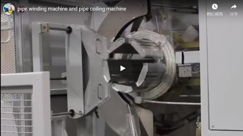
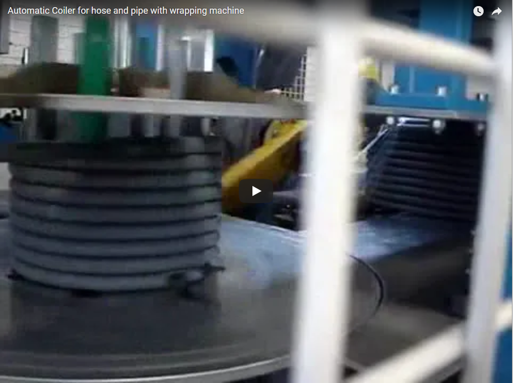
Executive summary We build automatic hose coil winding machines that take hose straight from the extruder, count the length, wind the coil, cut and strap it. A twin-station head switches coils without slowing the line. Our FCL-V400 series covers tube OD 4–30 mm and coil OD 300–500 mm on Siemens PLC control. This guide covers the process, specifications, coil-length sizing and how to match coil time to extrusion speed.
Table of Contents
- Winding process
- Specifications
- Coil sizing
- Cycle time
- Strapping and packing
- Controls
- Installation
- Selection checklist
- Engineering FAQ
- Next step
- Related reading
- Sources
How twin-station hose coil winding works
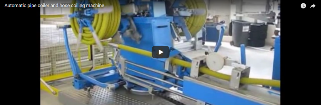
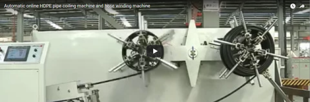
We built the two-head coiler in this 56 s video on an indexing turret. Each step below adds the engineering logic:
- 0–9 s, standby before the auto cycle. Both winding heads wait in position with the hose at the infeed before the automatic cycle starts. The twin-coil layout lets one head wind while the other is unloaded, so the extruder runs without stopping.
- 9–12 s, start. The active head starts turning and takes the hose into the centre.
- 12–30 s, winding. The hose is laid onto the active head layer by layer, with the feeding tube adjusted to hold coil tension. Multi-axis control lays the turns in ordered layers across the coil width, so the coil winds in a neat spiral.
- 30–56 s, layer build-up. The coil grows towards its set OD while the head keeps running. The length counter ends the coil at the programmed length, and the cutter separates the hose.
The station change between the two heads is the key design point. Winding continues on one head while the other coil is strapped and unloaded, so coil handling never sets the extrusion speed.
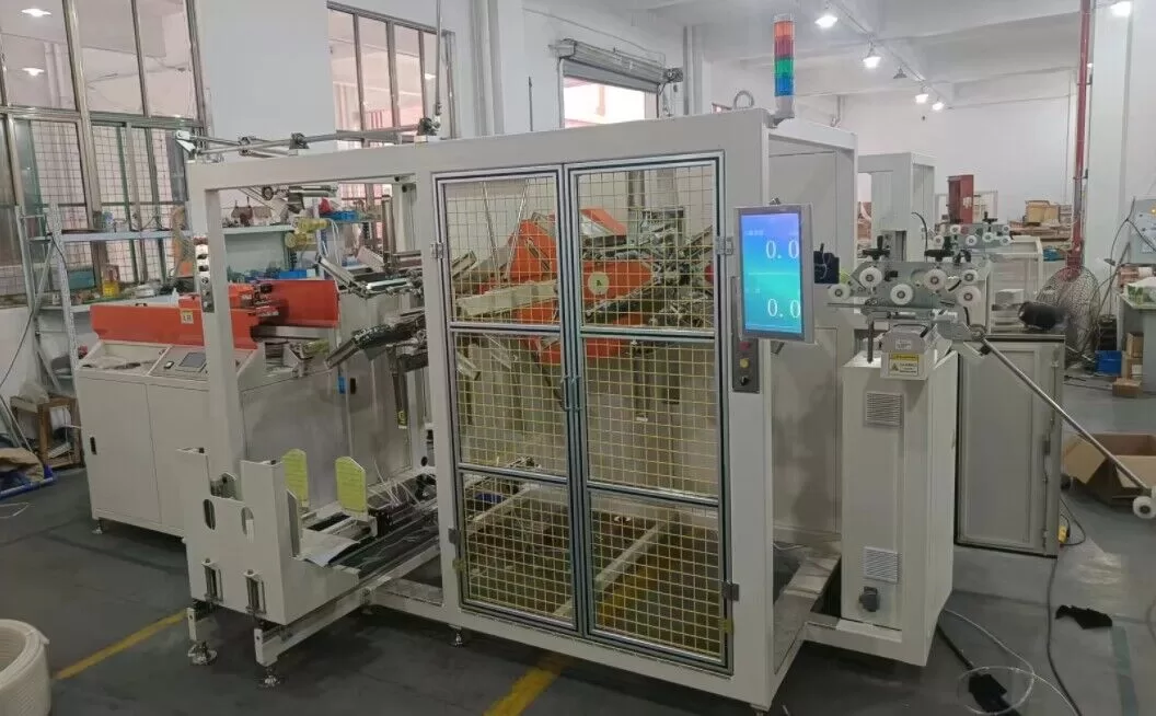
FCL-V400 hose coiler specifications
Values from our FCL-V400 automatic coiling and strapping machine, which covers tube OD 4–30 mm across three models:
| Parameter | FCL-V400A | FCL-V400B | FCL-V400C |
|---|---|---|---|
| Coil OD | Φ300–400 mm | Φ300–500 mm | Φ300–500 mm |
| Coil height | 40–120 mm | 80–200 mm | 150–300 mm |
| Coil ID | Φ200–300 mm | Φ250–400 mm | Φ250–400 mm |
| Tube OD | 4–10 mm | 10–20 mm | 15–30 mm |
| Set coil length (meter counter) | 10–50 m | 20–100 m | 20–100 m |
| Air supply | 6 bar | 6 bar | 6 bar |
Coil OD, coil ID and coil height are separate setting ranges, not paired values. Pick an ID and OD inside each range that leave room for the radial layers you need; the coil-sizing method below gives the count. The set coil length is the length per coil you enter on the HMI.
For larger coils, our FCL-V600 series winds coil OD 400–600 mm. Our FCL coiler range for larger pipe reaches 63 mm pipe OD and 1600 mm coil OD on the FCL1000.
Coil sizing: how much hose fits on one coil
Coil length is set by geometry, so check it before choosing the model:
- Radial layers = (coil OD − coil ID) ÷ 2 ÷ hose OD.
- Turns per layer = coil height ÷ hose OD.
- Length ≈ layers × turns per layer × π × mean coil diameter.
Worked example on FCL-V400A: 10 mm hose, coil OD 400 mm, ID 300 mm, height 80 mm. That gives 5 layers × 8 turns = 40 turns at a 350 mm mean diameter, about 44 m per coil. That sits inside the 10–50 m meter counter range.
Two more checks:
- Bend radius: the coil ID must be at least twice the hose’s minimum bend radius, taken from your hose datasheet.
- Corrugated hose: use the outer corrugation diameter as hose OD.
Coil cycle time matched to extrusion line speed
The coiler has to finish each coil within the time the extruder takes to produce it:
- Time per coil = coil length ÷ line speed. A 44 m coil at 25 m/min takes about 106 s, which is 34 coils/h.
- Station work (strapping, ejection and turret indexing) must fit inside that time on the second head.
- Coiling speed: our coiling-and-strapping machines are adjustable to the extrusion line speed, with coiling at 60 m/min or more.
Our engineering data for automatic coiling-and-strapping lines puts typical output at 40–60 coils per hour. The rate depends on coil size and the number of straps. Short coils at high line speed therefore need the strap count kept low.
Strapping and packing the hose coil
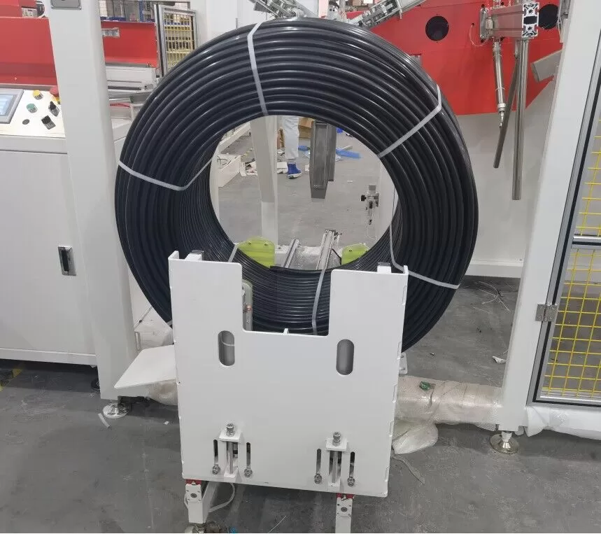
In this machine, “packing” means the coil is strapped so it holds its shape. Our FCL-V400 steps are:
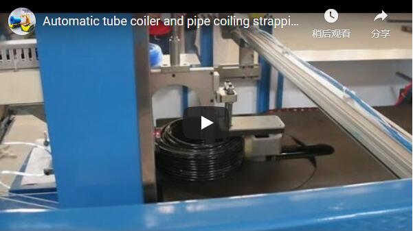
- Strapping: automatic PP tape at 2 or 4 positions around the coil.
- Coil ejection: automatic discharge of the strapped coil.
- Tension: the feeding tube is adjustable to set coil tension, so the turns stay tight without flattening soft hose.
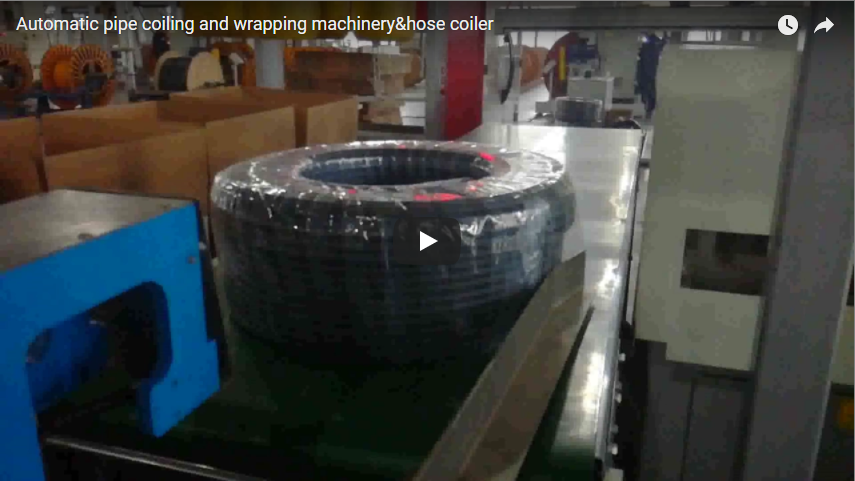
For film-wrapped or bagged coils, the strapped coil continues to a hose coil wrapping machine downstream.
PLC controls and length counting
The FCL-V400 runs on a Siemens control package:
| Component | Brand / function |
|---|---|
| PLC, HMI, inverter | Siemens |
| Encoder and transducer | Autonics, for length counting |
| Cylinders and solenoid valves | Airtac, 6 bar air |
| Switches, buttons, contactors | Schneider |
| Coil program | Length, OD and width set on the HMI |
The coil length is entered on the HMI and counted by the encoder, and each length is cut automatically. Coil OD and width are adjustable for product changes.
Installation at the extruder
We install the coiler in place of the manual winding stand at the end of the extrusion line:
- Position: after the haul-off, in line with the extrusion axis. The coiler cuts each length itself.
- Utilities: compressed air at 6 bar for the pneumatic winding baffle, cylinders and strapping.
- Speed match: coiling speed is set to the extrusion line speed, so both run at the same rate.
ISO 12100 sets the risk-assessment method. The applicable machinery standards depend on the destination market.
Selection checklist for a hose coil winding machine
Send these values with your request:
- Hose or pipe OD range, material (PE, PVC, corrugated, rubber) and minimum bend radius.
- Target coil length, coil OD, ID and height.
- Extrusion line speed in m/min, and single or twin line.
- Strapping: number of straps and tape type; film wrapping or bagging downstream.
- Available air supply and voltage at site.
Engineering FAQ
Q: Does the extruder have to stop at each coil change? A: No. On a twin-station coiler, the turret swaps heads and winding continues on the empty head while the full coil is strapped. Our FCL-V400 switches stations without reducing the extrusion line speed.
Q: Which hose sizes does the FCL-V400 cover? A: Tube OD 4–10 mm on the V400A, 10–20 mm on the V400B and 15–30 mm on the V400C. Coil OD runs from 300 mm up to 500 mm.
Q: How fast can the machine coil? A: Coiling speed follows the extrusion line, at 60 m/min or more. Typical output is 40–60 coils per hour, depending on coil size and the number of straps.
Q: How do I work out the hose length per coil? A: Multiply radial layers by turns per layer by π × mean diameter. A 10 mm hose on a 400 mm OD, 300 mm ID, 80 mm high coil gives about 44 m.
Q: What utilities does the coiler need? A: Compressed air at 6 bar and electrical power at site voltage. Give us the voltage and frequency with your request so the Siemens drive package is matched.
Next step
We configure the coiler for your extrusion line in three steps:
- Submit your layout drawing with hose OD, coil length and size, line speed and strapping needs to info@fhopepack.com.
- Receive a machine proposal within 48 hours, with model choice, coil-time check and strapping setup.
- Book a site survey to place the coiler after your haul-off.
Related reading
- Automatic hose coiler and strapping machine FCL-V400
- Automatic hose coiling machine FCL-V600
- Hose and pipe coiling and strapping machines
- Hose packaging machines
- Video: automatic hose coiling and strapping machine
- Video: high speed hose coiling machine
Sources
- FCL-V400 coil and tube ranges, meter counter, air supply, features, control components: FCL-V400 product page
- FCL-V600 coil OD range: FCL-V600 product page
- Horizontal FCL pipe OD and coil OD range: coiling and strapping machine page
- Coiling speed and coils-per-hour range: FHOPE internal engineering data
- Process steps and timestamps: our hose coil winding video on YouTube, 56 s
- Risk assessment: ISO 12100:2010
Last reviewed: 2026-10-03