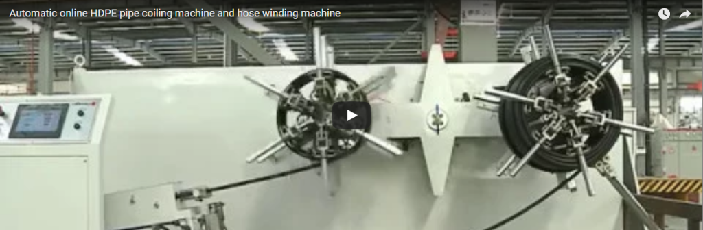
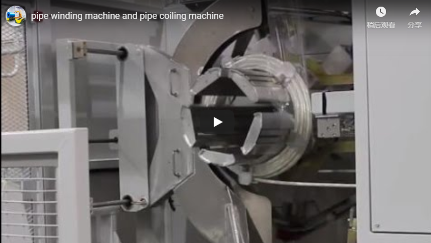
Executive summary Small-diameter plastic tubing and flexible hose require continuous, layer-wound coil formation directly from extrusion or rewinding pay-offs to eliminate tangling and surface abrasion. The automated tube coiler integrates a horizontal motor-driven turntable, a servo-synchronized traversing arm, a pneumatic vertical press head, and an automated transfer system that feeds coils directly into inline strapping and downstream shrink-wrapping stations. Standard sizing is dynamically engineered based on tube OD, batch target length, and permissible coil OD/ID ratios to integrate seamlessly with downstream secondary packaging.
Table of Contents
- What the video shows
- How the tube coiler works
- Coil size and layer calculation
- Strapping the coil
- Controls and safety
- Selection checklist for a tube coiler
- Engineering FAQ
- Next step
- Related reading
- Sources
What the video shows
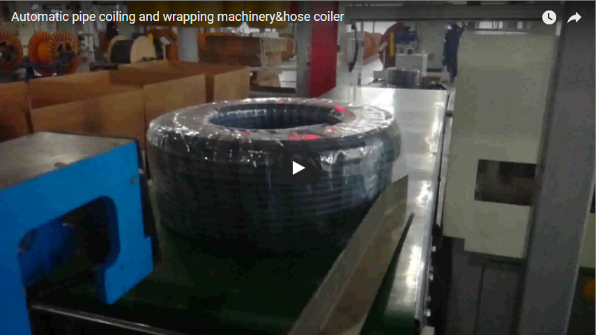
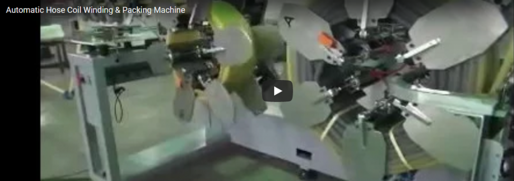
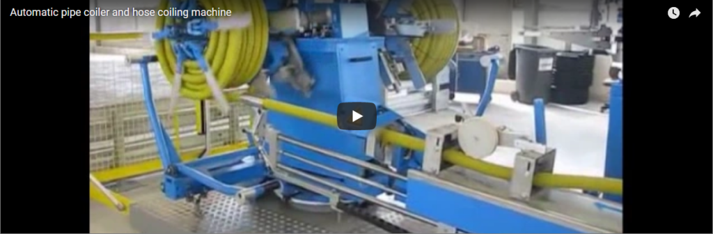
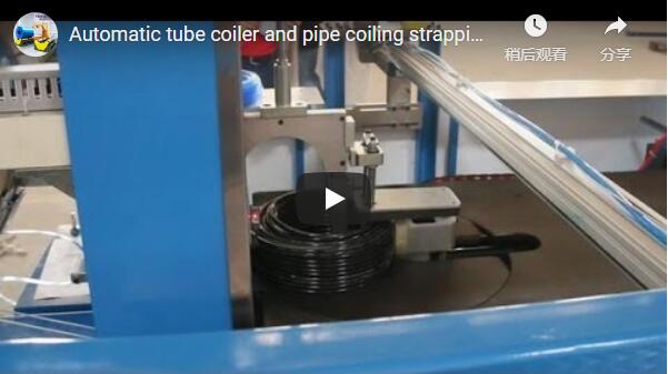
The operational video demonstrates a complete, fully automated small-bore tube coiling, strapping, and secondary packaging cell in factory trials:
- De-coiling and Active Tension Infeed: Flexible black polymer tube pays off smoothly from a primary supply reel through an accumulator dancer guide, dampening tension spikes before reaching the coiling spindle.
- Precision Traverse Coiling: The tube winds onto a central collapsing mandrel atop the horizontal rotary table. A traversing guide unit reciprocates synchronously across the winding width to guarantee snug, edge-to-edge parallel layering without crossing.
- Vertical Clamping Spindle Action: The overhead pneumatic press head descends over the wound coil, stabilizing outer turns and holding the bundle tightly compressed against the core to prevent coil expansion after cutting.
- Pneumatic Coil Push-Off and Transfer: Once the pre-set length is reached and the core collapses, an automated pneumatic pusher shifts the coiled bundle along a transfer table directly into the radial strapping station.
- Downstream Strapping and Shrink Tunnel Interfacing: The strapped coil is transferred downstream through an inline horizontal sealer and convective shrink tunnel, exiting as a fully enclosed, moisture-tight, transport-ready package.
How the tube coiler works
| Step | Mechanical Execution | Process Parameters |
|---|---|---|
| 1. Thread & Clamp | Tube leading end is locked into the internal mandrel clamp | Manual start or automated pneumatic jaw grip |
| 2. Synchronized Coiling | Turntable rotates while servo traverse reciprocates across width | Turntable speed: 20–120 RPM (VFD controlled); Line speed tracking |
| 3. Precision Metering | Rotary encoder monitors continuous extruded linear meterage | Cut-off accuracy: ±0.3% of total length |
| 4. Press & Core Collapse | Top pneumatic press head clamps coil down; inner mandrel retracts | Downward force: 150–400 N (pressure-regulated) |
| 5. Ejection & Strapping | Push arm shifts the bundle to strapping position for PP/PET ties | Cycle time: 15–25 seconds per transfer |
| 6. Inline Shrink Wrap | Strapped bundle transfers into horizontal sealer and heating tunnel | Continuous protective PE/POF film skin application |
The overhead press head acts as a stabilization clamp, preserving bundle density and square sidewalls so strapping bands remain parallel and flush. For configurations requiring dedicated high-speed protective spiral wrapping, explore our automatic pipe coiling and wrapping machine.
Coil size and layer calculation
Winding dimensions depend on the coil width (effective traverse stroke), tube outside diameter (OD), core diameter (ID), and target batch length. The geometric progression is modeled as follows:
- Turns per Layer:
N_turns = floor(W_coil / OD_tube) - Total Layers Required:
N_layers = ceil(Total_Turns / N_turns) - Coil Maximum Outside Diameter (OD):
OD_coil = ID_core + 2 × (N_layers × OD_tube) - Mean Coiling Diameter:
D_mean = (ID_core + OD_coil) / 2 = ID_core + (N_layers × OD_tube) - Total Wound Length:
L_total = N_turns × N_layers × π × D_mean
Worked Example (20 mm OD Flexible Tube, 120 mm Coil Width, 400 mm Core ID):
| Parameter | Mathematical Formulation | Metric Value |
|---|---|---|
| Turns per layer | 120 mm / 20 mm |
6 turns |
| Calculated layers | Target batch for ~200 m length | 15 layers |
| Total bundle turns | 6 turns/layer × 15 layers |
90 turns |
| Coil OD | 400 mm + 2 × (15 × 20 mm) |
1,000 mm |
| Mean diameter (D_mean) | 400 mm + (15 × 20 mm) |
700 mm (0.70 m) |
| Total finished length | 90 × π × 0.70 m |
~197.9 m |
Note: Flexible plastic tubes with thin wall thicknesses experience minor transverse ovalization under winding tension; an empirical compaction coefficient (typically 0.94–0.98) should be factored into calculated OD limits to meet packaging carton tolerances.
Strapping the coil
| Engineering Factor | Operational Function | Process Control Range |
|---|---|---|
| Straps per Coil | Prevents structural layer unwinding during logistics handling | 2, 3, or 4 radial PP/PET straps |
| Strap Positioning | Symmetric radial placement around the coil circumference | 90° or 120° rotational index |
| Strap Tensioning | Secures layers firmly without wall crushing or lumen pinching | 50–250 N (calibrated per tube durometer) |
| Press Clamping Head | Maintains planar sidewall flatness while tensioning and welding | Pneumatic pressure: 0.4–0.6 MPa |
Flexible, thin-walled elastomer tubes (e.g., polyurethane, silicone, soft PVC) require lower tensile strap settings and widened strapping pads compared to rigid HDPE or PPR pipe. Mechanical strapping limits are dialed in during factory commissioning using material samples.
Controls and safety
High-speed rotating turntables, traversing guides, and pneumatic vertical cylinders introduce crushing and pinch points if unguarded. Safe operation relies on a multi-tier protective structure:
- Safety Interlocks and Guarding: Fully interlocked transparent safety doors enclosing rotating reels, complying with ISO 14119. Opening an enclosure triggers an immediate Category 0 emergency stop via safety relays.
- Pneumatic Pressure Trapping & Residual Exhaust: Clamping cylinders incorporate pilot-operated check valves to avoid uncommanded downward drift in the event of upstream compressed air loss, paired with controlled residual dump valves for maintenance lock-out.
- CE Machinery Harmonization:
- ISO 12100:2010: Comprehensive hazard identification and risk assessment across all coiling and indexing modes.
- EN 415-10:2014: Safety mandates addressing packaging machines, covering strapping head zones, feeding tracks, and integrated transfer modules.
- EN 60204-1: Electrical safety, emergency stop circuits (Cat. 4 / PL e), and thermal motor overcurrent protection.
Selection checklist for a tube coiler
- Tube Profile: Tube outside diameter (OD), inside diameter (ID), wall thickness, and polymer grade (PE, PU, PVC, PA, PEX).
- Coil Geometric Constraints: Required inner diameter (ID_core), maximum allowed outer diameter (OD_max), and traverse width (W_coil).
- Production Velocity: Extrusion line speed (m/min) or target completed coils per hour.
- Cutting & Tie Specifications: Manual vs. automatic flying cut; 2, 3, or 4 radial straps (polypropylene or polyester).
- Downstream Interfacing: Standalone coiler vs. integrated transfer to automatic strapping, stretch wrapping, or shrink packaging tunnel.
- Facility Utilities: Factory pneumatic supply (0.5–0.7 MPa clean, dry air) and available electrical service (380V/480V 3-phase, 50/60 Hz).
Engineering FAQ
Q: What is the maximum linear coil length this machine can handle? A: Length capacity is governed by the allowable coil outside diameter (OD). For instance, 15 layers of 20 mm OD tube wound on a 400 mm ID core yields approximately 198 m at 1,000 mm OD. Adjusting the core diameter or coil width allows longer continuous runs.
Q: How does tube wall thickness influence the finished coil diameter?
A: Thin-walled tubes compress slightly under winding tension, resulting in a finished OD marginally smaller than theoretical calculations. Heavy-wall or rigid pipes do not yield, following the direct geometric formula: OD_coil = ID_core + 2 × (N_layers × OD_tube).
Q: Why is an overhead vertical press head required during strapping? A: Tubes wound under rotational tension exhibit elastic recovery. The press head holds the bundle compressed against the turntable face, eliminating internal stresses and preventing outer-layer crowning while the strapping bands are tensioned and friction-welded.
Q: Can the machine coil soft braided hose without collapsing the inner passage? A: Yes. The line utilizes a closed-loop pneumatic dancer arm to regulate winding tension below the hose deformation threshold, combined with lower strapping strap tension settings (50–100 N).
Q: Can this coiler run inline directly with continuous extrusion lines? A: Yes. By integrating a vertical or horizontal accumulator (dancer tower), the extrusion line continues discharging at constant velocity while the coiler performs automatic cutting, coil transfer, and reset cycles.
Next step
Streamline your tube and hose packaging workflow through our engineered integration process:
- Submit Line Specifications: Send tube dimensions, resin specifications, target coil geometries, and extrusion line speeds to info@fhopepack.com.
- Receive Engineering Layout & Proposal: Our technical team delivers an optimized mechanical layout, strapping cycle calculation, and formal quotation within 48 hours.
- Factory Acceptance & Line Integration: Confirm coil presentation through physical material trials and schedule on-site commissioning with your extrusion line.
Related reading
- Pipe packing machines
- HDPE pipe coil and hose wrapping machine solutions
- Double wall corrugated hose coiling and strapping systems
- Hose stretch wrapping machine for protective coil packaging
Sources
- Machine technical data: FHOPE Packaging Engineering Division, Tube & Hose Automation Series.
- Mathematical coiling formulations: FHOPE Machine Geometric Calculator Standard (Issue Rev. 4).
- Industrial machine reference: FHOPE Automated Pipe Packaging Line Series.
- Safety compliance standards: ISO 12100:2010 Safety of machinery — General principles for design, EN 415-10:2014 Safety of packaging machines — General requirements.
Last reviewed: 2026-10-04