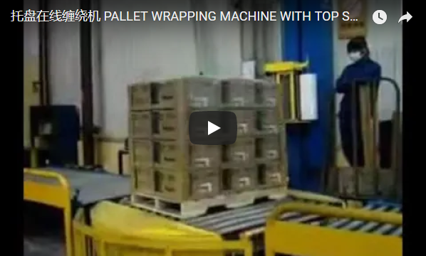
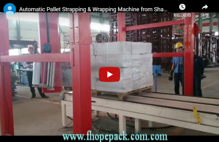
Executive summary An automated pallet top press stabilizes tall, column-stacked, or compressible goods against lateral centrifugal displacement and shifting during high-speed wrapping or cross-strapping. The integrated system presented here conveys palletized white cylindrical rolls beneath a rigid gantry frame, executes controlled vertical platen clamping, maintains constant surface pressure through the securing sequence, and discharges the stabilized unit downstream. Clamping force and platen pad composition are calculated directly from pallet gross weight, roll deformation limits, and packaging friction coefficients, preventing edge crush while ensuring load integrity.
Table of Contents
- System Architecture and Operational Overview
- Sequential Cycle Breakdown
- Pallet Payload and Structural Load Sizing
- Safety Engineering, Machine Guarding, and Compliance
- Selection Checklist for Pallet Line with Top Press
- Engineering FAQ
- Next Step: System Sizing and RFQ
- Related Reading
- Sources and Normative Standards
System Architecture and Operational Overview
Palletized industrial rolls stacked on end exhibit an inherently high center of gravity and low interlayer friction. Without vertical restraint, rotational acceleration during turntable or rotary-ring wrapping causes layer shifting, telescoping, and loose strap retention.
[Infeed Conveyor] ──> [Optical Centering Gate] ──> [Rigid Portal Gantry]
                                                            │
                                                  [Pneumatic/Servo Platen]
                                                  [Controlled Down-Force]
                                                            │
[Downstream Discharge] <── [Strap / Film Wrap Cycle] <──────┘
The system comprises three core mechanical modules:
- Structural Portal Gantry: Heavy-duty structural steel box-section gantry (blue finish) engineered to absorb cyclic vertical clamping loads up to 5000 N without structural deflection.
- Vertical Press Platen: Guide-column supported press beam equipped with pneumatic cylinders or electric linear actuators, complete with high-friction, non-marking polyurethane contact facing.
- Integrated Control Station: Standalone electrical cabinet housing the system PLC, variable frequency drives (VFD), and a swivel-mounted color touch HMI displaying continuous cycle telemetry and optical safety light barrier status.
Sequential Cycle Breakdown
The operational cycle is fully synchronized between the material handling conveyor, optical position sensors, and the press assembly logic:
| Phase | Sub-Cycle Function | Process Description | Typical Duration |
|---|---|---|---|
| Phase 1: Infeed & Indexing | Pallet positioning | Powered roller conveyor transfers roll pallet into gantry core; retroreflective PE sensors execute slowdown and positive mechanical/brake stop. | 15–20 s |
| Phase 2: Platen Descent & Clamp | Controlled stabilization | Dual guided pneumatic cylinders drive platen downward; soft-docking limit switch triggers variable pressure holding (0.15–0.40 MPa). | 8–12 s |
| Phase 3: Primary Securing | Wrapping / Strapping | Vertical clamping force maintains roll column geometry while rotary packaging mechanism applies film or tensioned PET straps. | 15–25 s |
| Phase 4: Platen Retraction & Outfeed | Line clearance | Top press retracts to upper home limit; rod-lock engages; conveyor discharges stabilized load to downstream staging. | 8–10 s |
| Phase 5: Diagnostics & Ready State | HMI verification | Controller performs optical clearance verification; status indicator transitions to green ready state. | Continuous |
Pallet Payload and Structural Load Sizing
Conveyor roller spacing, drive gearmotor torque, and gantry column sizing are governed by the maximum gross unit load rather than nominal averages. Below is a structural load calculation matrix for typical vertical roll configurations:
| Parameter | Unit Value (Metric) | Engineering Calculation Basis |
|---|---|---|
| Roll Arrangement per Layer | 4 units | 2 × 2 matrix, vertical roll axis |
| Layer Count | 2 layers | Total 8 rolls per pallet base |
| Unit Mass per Roll | 50.0 kg | Nominal roll weight (paper/film/foil stock) |
| Total Net Goods Mass | 400.0 kg | 4 rolls/layer × 2 layers × 50.0 kg/roll |
| Industrial Wooden Pallet Tare | 25.0 kg | Four-way entry heavy-duty pallet (1200 × 1000 mm) |
| Gross Static Load on Conveyor | 425.0 kg | 400.0 kg (goods) + 25.0 kg (pallet) |
| Recommended Dynamic Structural Sizing | 637.5 kg | Sizing with dynamic safety factor k = 1.5 |
| Applied Vertical Platen Clamping Force | 1200–1800 N | Preset based on roll core axial crush limits |
To prevent core collapse or surface imprint on sensitive goods, top platen downward force must satisfy the non-marking equilibrium criterion:
P_contact = F_clamping / A_contact ≤ P_permissible
Where:
P_contact: Actual contact pressure exerted on roll tops (kPa).F_clamping: Total downward thrust from pneumatic/servo cylinders (N).A_contact: Total effective contact area across roll end faces (cm²).P_permissible: Maximum yield pressure before substrate deformation (typically ≤ 30 kPa for hollow fiber or core-wound paper rolls).
Controls and Safety Engineering
A descending overhead beam introduces severe pinch and shear hazards. The machine design incorporates multilayer physical, pneumatic, and electrical safety measures compliant with international industrial standards:
[Emergency Stop Circuit / Safety Gate Open]
                    │
       (PL d / Cat 3 Dual Channel)
                    │
  ┌─────────────────┴─────────────────┐
  ▼                                   ▼
[Pneumatic Exhaust: Safe Venting] [Pneumatic Rod Lock: Mechanical Drop Stop]- Access Prevention and Zone Monitoring: Optical Type 4 Safety Light Curtains guard infeed and outfeed openings with integrated muting logic, preventing human entry while allowing pallet indexing without nuisance trips.
- Mechanical Drop Protection: Lift cylinders feature integrated spring-applied, pneumatic-release rod locks (drop arrestors). In the event of total electrical power loss or compressed air line rupture, the platen mechanically locks in place within ≤ 15 mm of travel.
- Regulatory Compliance:
- ISO 12100:2010: Systematic safety risk assessment for machine assemblies.
- EN 415-10:2014: Safety requirements for automated packaging lines.
- EN ISO 13849-1: Functional safety design achieving Category 3, Performance Level d (PL d) architecture on all safety-relevant control functions.
- OSHA 1910.147: Padlockable pneumatic and electrical Lockout/Tagout (LOTO) energy isolation points.
Selection Checklist for Pallet Line with Top Press
Evaluate the following operational parameters before finalizing system configuration:
- Pallet Envelope Geometry: Minimum and maximum pallet dimensions (
Length × Width × Height, e.g., 800 × 1200 mm to 1200 × 1200 mm; height range 600–2400 mm). - Maximum Unit Load Weight: Peak pallet gross weight (including pallet tare) to establish conveyor motor power and frame gauge.
- Product Crush Sensitivity: Core yield strength and maximum allowable surface clamping pressure (
kPaorN/cm²). - Platen Interface Requirement: Selection between smooth vulcanized EPDM rubber, cross-linked PE foam, or non-stick Teflon pad facing.
- Packaging Process Integration: Stretch wrapping only, horizontal/vertical strapping only, or integrated wrap-and-strap dual operations.
- Throughput Demands: Required line speed (pallets/hour) to balance cylinder transit velocity with cushioning dampeners.
- Conveyor Elevation and Interface: Top-of-roller (TOR) elevation standard (typically 450–650 mm) matching upstream/downstream transfer conveyors.
Engineering FAQ
Q: What is the primary operational purpose of the top press on this line? A: It provides a stable vertical pre-load downward onto loose, non-interlocked roll assemblies. This counteracts centrifugal displacement from rotary wrappers and prevents top-layer lifting during high-tension strapping cycles.
Q: How is clamping force calculated to prevent crushing soft products? A: Downward force is regulated via an automated electro-pneumatic proportional regulator. By programming the roll diameter and product type into the HMI, the PLC throttles line pressure (0.1–0.6 MPa) so platen face pressure remains below the substrate’s elastic crush limit.
Q: What stops the heavy press cross-beam from dropping if compressed air fails? A: Dual safety features are installed: an internal pneumatic pilot check valve holding cylinder volume, backed by an external fail-safe mechanical brake (pneumatic rod lock) that clamps the guide shaft immediately upon pressure drop.
Q: Can this gantry structure handle variable pallet heights on the same line? A: Yes. An optical ultrasonic or time-of-flight laser sensor continuously reads incoming pallet height during infeed. The cylinder stroke auto-slows before contact to execute smooth soft-docking regardless of layer count variations.
Q: What PLC and control platforms are standard? A: Standard lines are equipped with Siemens S7-1200/1500 or Rockwell Allen-Bradley Micro850/CompactLogix architectures paired with an industrial 7-inch to 10-inch color touchscreen interface.
Next Step: System Sizing and RFQ
Implement a high-stability pallet packing solution tailored to your plant layout in three structured engineering phases:
- Submit Layout and Product Profiles: Transmit your facility DWG/PDF layout along with roll dimensions, layer configurations, and maximum gross pallet weight to info@fhopepack.com.
- Receive Comprehensive Proposal within 48 Hours: Our engineering division will supply an equipment layout drawing, complete clamping force calculations, throughput cycle simulation, and exact platen pad material options.
- Schedule an Engineering Site Assessment: Book a physical or virtual technical walkthrough with our project engineering team to confirm floor anchoring specs, infeed interface heights, and safety integration boundaries.
Related Reading
- Automatic Strapping Machines: High-Tension Pallet Securing Systems
- Rotary Ring and Turntable Stretch Wrappers with Pneumatic Top Clamps
- Automated Roll and Carpet Packaging Automation Lines
Sources and Normative Standards
- Technical Equipment Dataset: FHOPE Engineering Packaging Division, 2026-10-04
- Structural Mechanics Reference: Industrial Pallet Load Stability Guidelines (CEN/TS 14884)
- Operational Machine Demonstration: FHOPE Official Packaging Systems Media
- Safety Machine Directives: ISO 12100:2010 General Principles for Design – Risk Assessment
- Packaging Machinery Specifics: EN 415-10:2014 Safety Requirements for General Packaging Machines
Document Revision: Rev 3.2 | Last Technical Review: 2026-10-04