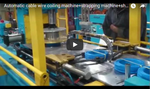
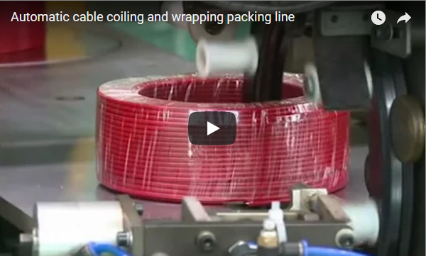
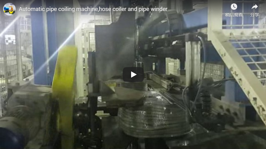
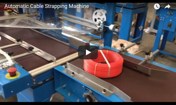
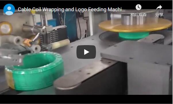
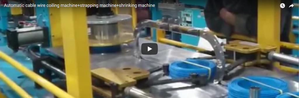
Executive summary This automatic vertical-axis cable and hose coiling system engineered for high-precision winding, automated coil compaction, and seamless roller-conveyor transfer. Designed to integrate directly with continuous extrusion, braiding, or cut-to-length pay-off lines, this system handles coil outer diameters (OD) from 650 to 1,150 mm at line speeds up to 70 m/min. With an adjustable-diameter collapsible coiling head and integrated pneumatic pusher, the line prevents inner-core deformation while accelerating cycle turnover. Every system is engineered to project-specific product stiffness and footprint requirements.
Table of Contents
- System Overview & Line Integration
- Operational Sequence & Mechanical Kinematics
- Technical Specifications & Working Range
- Secondary Packaging: Strapping & Stretch Wrapping
- Engineering Selection Checklist
- Machine Safety Architecture & Standards
- Automation Upgrades & In-Line Labeling
- Engineering FAQ
- Project Sizing & Procurement Next Steps
- Related Solutions
- Technical Sources
System Overview & Line Integration
An automatic cable coiling machine bridges the gap between continuous upstream production (such as wire extrusion, hose vulcanization, or payout racks) and downstream warehouse packaging. It draws flexible conduit, hydraulic hose, industrial cable, or plastic pipe through a tension-controlled path, winding the product onto an expanding rotary mandrel to form dense, dimensionally uniform coils.
Once the pre-set length is reached, the machine secures the coil, collapses the mandrel segments, and pneumatically discharges the package onto a gravity or powered roller conveyor.
Because coil dimensions, hoop stress, and material flexural moduli differ significantly across thermoplastic pipes and elastomeric hoses, our machine configurations are tailored per application. The values outlined below reflect our standard engineering envelope rather than single-point limitations of the demonstration unit.
Operational Sequence & Mechanical Kinematics
The operational video documents the cycle of a vertical-spindle coiling cell transitioning from winding to discharge:
- Mandrel Clamping & Infeed Indexing: The sequence begins at the vertical coiling station. A heavy-duty blue and white structural frame houses the rotary drive and pneumatic top-clamp assembly. A four-segment collapsible center mandrel expands to the target inner diameter (ID), while a top retaining disk lowers pneumatically to confine the coil width during high-speed rotation.
- Servo-Synchronized Traversing: The flexible conduit passes through dual guide rollers mounted on a reciprocating traverse screw. The traverse pitch matches the product outer diameter (OD) per spindle revolution, ensuring level-layer winding without overlapping, entangling, or sidewall crowning.
- Controlled Deceleration & Top-Plate Lift: As the pre-programmed length sensor triggers the end-of-cycle limit, the main spindle drive decelerates under variable frequency drive (VFD) braking. The pneumatic overhead clamp retracts vertically to clear the transfer envelope.
- Mandrel Collapse & Ejection: The internal mechanical linkages of the mandrel collapse radially inward. This relieves residual radial hoop stress from the tightly wound coil, preventing surface abrasion on the inner wraps.
- Pneumatic Discharge & Conveyor Exit: A horizontal pneumatic sweep arm actuates across the coiling table, pushing the finished black coil smoothly off the low-friction turntable platform and transferring it onto an adjacent roller conveyor for downstream binding, wrapping, or palletizing.
Technical Specifications & Working Range
For comprehensive technical documentation, refer to our primary equipment portfolios: the automatic pipe coiler machine and the high-output cable coiling and wrapping machine.
| Engineering Parameter | Standard Operating Envelope | Engineering Notes |
|---|---|---|
| Pipe / Cable Outer Diameter (OD) | 16 – 32 mm | Smaller cross-sections require fine-wire guide rollers |
| Coil Inner Diameter (ID) | 400 – 540 mm | Segmented expanding mandrel with stepless adjustment |
| Coil Outer Diameter (OD) | 650 – 1,150 mm | Constrained by turntable safety guard envelope |
| Coil Package Width (Height) | 200 – 320 mm | Set by overhead clamp cylinder stroke limit |
| Maximum Coil Weight | 10 – 40 kg | Dynamic rating under standard spindle bearing load |
| Coiling Linear Speed | Up to 70 m/min | Synchronized to line master speed or dancer loop |
| Optional Ring Wrapper Speed | Up to 200 m/min | Through-the-eye orbital stretch wrapping module |
| PP Strapping Width | 10 mm (9–12 mm compatible) | Ultrasonic or thermal heat-weld binding head |
| Operating Pneumatics | 0.5 – 0.7 MPa | Clean, dry compressed air supply required |
Note: Wrapping travel rates (up to 200 m/min) and PP strapping parameters apply only when downstream automated packaging modules are physically docked with the coiler exit.
Throughput calculation is governed by product mechanical properties. Rigid multi-layer pipe demands controlled deceleration arcs, whereas flexible braided cable permits rapid indexing. Real output is determined based on sample test data and shift parameters.
Secondary Packaging: Strapping & Stretch Wrapping
While the core demonstration focuses on coiling and lateral discharge, complete automated lines typically dock the coiler output with automated binding stations:
- Radial Strapping Unit: Uses polypropylene (PP) or polyester (PET) strapping applied through the eye of the coil in 2, 3, or 4 radial positions. This prevents coil expansion caused by residual mechanical spring-back in stiff PE/PEX pipes.
- Orbital Through-the-Eye Wrapping: Employs LLDPE stretch film or woven tape to encapsulate the annular body. This provides complete dustproofing, moisture resistance, and ultraviolet (UV) shielding during outdoor transit.
- Conveyor Handshake: The exit roller bed is matched in height (standard 750–850 mm ± 50 mm) and electrically interlocked via 24V dry-contact relays or industrial Ethernet (PROFINET/EtherNet/IP) to downstream plant logistics.
Engineering Selection Checklist
To allow our application engineers to deliver an accurate sizing proposal, compile the following operational parameters:
- Product Specifications: Pipe/cable nominal OD, minimum allowable bend radius (R_min), cross-sectional rigidity, and linear density (kg/m).
- Target Coil Envelope: Minimum and maximum Coil ID, Coil OD, and coil axial width.
- Line Dynamics: Upstream line delivery speed (m/min), continuous extrusion versus intermittent batch cutting, and required cycle time per coil.
- Securing Method: Requirement for manual tie-off, automated PP strapping, orbital stretch film wrapping, or adhesive tape tabbing.
- Material Handling Interface: Discharge roller centerline height, line direction (left-to-right vs. right-to-left), and accumulator length.
Machine Safety Architecture & Standards
High-speed rotary coiling and pneumatic ejection present dynamic mechanical pinch points. Equipment engineering complies strictly with destination-market machine directives:
-
International Standards: Conforms to ISO 12100:2010 for holistic risk assessment and machine risk reduction, alongside EN 415-10 covering comprehensive safety guidelines for packaging machines and associated secondary lines.
-
Zero-Pressure Pneumatic Safety: Ejection cylinders and top clamps utilize pilot-operated check valves to prevent gravity-induced dropping during an emergency stop (E-stop) or facility air pressure loss.
-
Lockout/Tagout (LOTO): Maintenance points, including manual mandrel adjustment mechanisms and film reel spindles, are fully accessible only after machine isolation under OSHA 1910.147 / EN 1037 protocols.
Automation Upgrades & In-Line Labeling
For zero-labor packaging workflows, the coiling cell can be equipped with peripheral automation:
- Under-Film Automatic Label Inserter: Positions barcode, RFID, or batch labels directly against the outer wraps prior to orbital wrapping. The clear stretch film encapsulates the label, shielding it from transit friction, moisture, and tearing.
- Automated Cut-and-Transfer: An integrated pneumatic shear or circular blade cleanly parts the tube at precise target lengths measured by high-resolution optical encoders, eliminating manual operator intervention.
- Dual-Spindle Turret System: For uninterrupted extrusion lines operating above 50 m/min, a dual-mandrel indexing turret switches spindles instantly once a coil reaches capacity.
Engineering FAQ
Q: Can this system wind both flexible elastomeric hose and rigid PVC/PE pipe? A: Yes. Changing between materials requires setting the corresponding winding tension, adjusting the traverse guide pitch to match the new OD, and repositioning the collapsible mandrel segments to ensure the material does not buckle below its minimum bend radius.
Q: How does the collapsible mandrel prevent surface damage to fine cable jackets? A: When winding finishes, internal toggle links collapse the mandrel segments radially inward by 15–25 mm. This removes all circumferential contact stress before the pneumatic sweep arm activates, preventing scuffing or drag marks.
Q: How is the pitch of the traversing guide synchronized with spindle rotation? A: The traversing assembly is driven by an independent servo motor electronically geared to the main spindle encoder. Pitch adjustments are configured directly via the HMI touchscreen without mechanical gear changes.
Q: What is required to receive a formal system proposal? A: Provide your product drawing, material specification, minimum and maximum coil dimensions, and upstream line speed. We generate layout drawings and utility load requirements based on these parameters.
Project Sizing & Procurement Next Steps
We execute custom coiling and packaging line projects through a structured 3-phase engineering review:
- Parameter Submission: Forward your line layout, target coil matrix (ID, OD, Width, Weight), and product mechanical data to info@fhopepack.com.
- Technical Proposal (Within 48 Hours): Receive a comprehensive technical quotation, including layout footprint drawings, line cycle time analysis, and utility schematics (electrical and pneumatic).
- Design Verification & FAT: Confirm conveyor transfer height, safety interlocks, and infeed line handshakes, followed by full Factory Acceptance Testing (FAT) with your raw materials prior to dispatch.
Related Solutions
- Automatic Cable & Wire Coiling and Binding System
- Automatic Pipe Coiling and Stretch Wrapping Line for Flexible Hose
- Economic Cable Coil Packaging Machinery: Technical Specs and Cycle Setup
- Industrial HDPE Pipe Coil and Hose Wrapping Solutions
- Small-Diameter Wire and Cable Coil Packing Systems
- Heavy-Duty Horizontal and Vertical Stretch Wrapping Systems
Technical Sources
- Reference channel: Fhopepack on YouTube
- Primary Line Documentation: Fhopepack Automatic Pipe Coiler Machinery; Cable Coiling & Packaging Systems
- Applicable Safety Standards: ISO 12100 (Risk Assessment & Reduction); EN 415-10 (Packaging Machines Safety); OSHA 1910.147 (Control of Hazardous Energy)
- Proposal Protocol: Official engineering review and proposal turnaround standard (48 hours)
Last reviewed: 2026-11-05