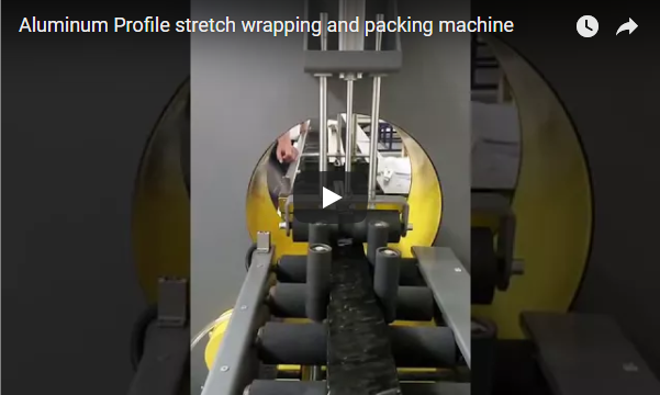
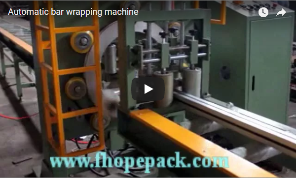
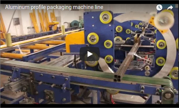
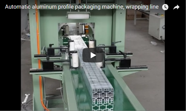
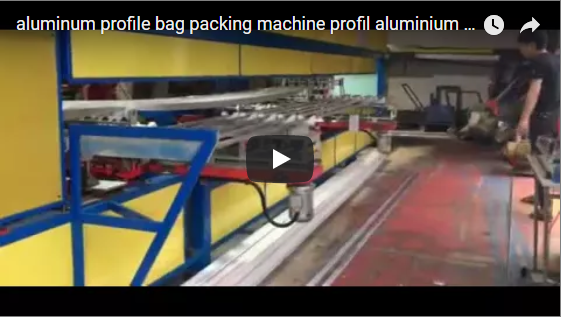
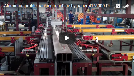
Executive Summary An automated aluminum profile packing line bridges the physical throughput gap between high-speed extrusion presses and downstream logistics. By replacing manual handling with synchronized gantry stacking, optical piece-counting, and automated kraft paper/PE surface wrapping, the line eliminates cosmetic drag marks, prevents bundling miscounts, and protects anodized or powder-coated finishes at line speeds up to 600+ profiles per hour.
The system integrates continuous profile in-feed, automated batch counting, servo-driven layer nesting, and tension-controlled protective wrapping into a cohesive, uninterrupted packaging cell. Designed specifically for architectural, industrial, and solar aluminum extrusions, the line ensures zero metal-to-metal dragging throughout the entire transfer and bundling cycle.
Table of Contents
- Why Automate Profile Packing
- Line Stations & Kinematic Workflow
- Bundle Make-Up & Nesting Geometry
- Covering and Taping Automation
- Cycle Time & Throughput Output Check
- Engineering Selection Checklist
- Safety & Compliance Standards
- Engineering FAQ
- Next Step & Technical Consultation
- Related Reading
- Sources
Why Automate Profile Packing
Manual handling in aluminum packaging introduces two persistent failure points: micro-abrasions and count discrepancies.
When operators lift, drag, and stack extrusions manually, friction causes fine galling, scuffing, and coating penetration on anodized, polished, and powder-coated surfaces. Furthermore, manual counting on high-output shifts leads to bundle quantity errors, triggering customer rejection or costly repacking.
An automated packaging cell resolves these issues by replacing dynamic sliding contact with pure vertical pick-and-place trajectories:
- Zero Scuffing: Profiles are gripped by non-marking elastomers (Shore A 55–60 vulcanized polyurethane or silicone) and transferred with controlled servo acceleration and deceleration.
- 100% Count Accuracy: Optical sensor arrays verify piece counts prior to gantry transfer, eliminating under- or over-shipment.
- Consistent Packaging Density: Controlled clamping ensures predictable, tight bundle dimensions suitable for automated warehouse racking.
Line Stations & Kinematic Workflow
The automated line is organized into four verified, PLC-synchronized operational sections:
[In-Feed & Saw Run-Out] │ ▼ [Station 1: Gantry Stacking] (Lift: 0.512 m/s, Spacer Insertion) │ ▼ [Station 2: Protective Film Applicator] (Inline Taping, Zero Manual Trimming) │ ▼ [Station 3: Collation & Active Roller Transfer] (Self-Adjusting Aperture, Non-Stop Profiles) │ ▼ [Station 4: Continuous Profile Bagging] (10–50 m/min, 6000 mm Baseline Envelope) │ ▼ [Discharge to Strapping & Logistics]
1. Stacking Gantry Station
Directly receiving profiles from the collation table, a Cartesian servo gantry executes layer-by-layer bundle formation. Equipped with mechanical contour clamps or vacuum tooling, the hoist mechanism operates at a calibrated lift speed of 0.512 m/s. Automated timber or EVA foam feeder magazines insert protective dunnage between stacked layers on demand to eliminate direct contact between profile faces.
2. Surface Film Applicator Station
This module applies surface-protection film and adhesive tape directly to the extrusions in a continuous pass. By automating film unwinding, tensioned lamination, and precision transverse cutoff, the station completely eliminates the manual trimming operator position previously required on semi-automated finishing lines.
3. Bundle Collation and Active Roller Transfer Station
Engineered on a rigid, compact structural steel frame, this section uses powered roller conveyors to govern bundle in-feed and out-feed. Profile bundles are driven forward through a set of self-centering, automatically opening and closing roller assemblies. This dynamic aperture control enables profile bundles of differing cross-sectional dimensions to pass consecutively without stopping the line for mechanical changeover.
4. Continuous Profile Bagging Station
The terminal packaging cell encloses single profiles or pre-formed mini-bundles into protective sleeve tubing:
- Compatible Bagging Media: BOPP or Polyethylene (PE) tubular films.
- Film Roll Dimensions: Outer Diameter (OD) 100–200 mm; Core Inner Diameter (ID) 75 mm; film thickness 30–60 µm.
- Tubing / Profile Capacity: Sleeve outer diameter OD 9.5–50 mm; handling feed speed adjustable from 10 to 50 m/min.
- Standard Dimensional Boundary: Standard tooling accommodates profile lengths up to 6000 mm. Extrusions exceeding 6000 mm require custom extended in-feed and out-feed engineering verification.
- Utility Ratings: Operating pneumatic supply of 5–7 bar; main drive power supply 380V, 3-phase, 60Hz.
Bundle Make-Up & Nesting Geometry
Bundle stacking geometry depends on cross-sectional symmetry, wall thickness, and surface protection requirements. For basic rectangular profiles, layer calculations follow standard clearance formulations:
Pieces per layer ≈ (Bundle target width – 2 × Clearance) ÷ Profile width
Pieces per bundle = Pieces per layer × Target layers
For asymmetrical profiles such as L-angles or U-channels, the PLC recipe activates a 180° alternating rotation sequence to nest profiles, maximizing bundle rigidity and package density.
| Parameter | How It Is Set | Documented Basis |
|---|---|---|
| Profile length | Bagging head is built for 6000 mm profiles; longer stock is quoted per project | bagging station data |
| Bagging throughput | 10–50 m/min, set by profile section and bag film thickness | bagging station data |
| Bag film | BOPP/PE, roll OD 100–200 mm, ID 75 mm, thickness 30–60 µm | bagging station data |
| Bag tube | Tube OD 9.5–50 mm, matched to bundle envelope | bagging station data |
| Air supply | 5–7 bar | bagging station data |
| Stacking lift | Gantry lift speed 0.512 m/s | stacker data |
| Pieces per layer, layer count, bundle weight | Calculated from the customer drawing; not a catalogue value | derived per project |
— | :— | :— | | Profile Section | 50 mm × 50 mm L-Angle | 15 mm to 250 mm cross-section | | Target Bundle Width | 300 mm | 150 mm to 600 mm max | | Pieces per Layer | 6 pieces (flat) / nested per setup | Configurable in PLC HMI recipe | | Layer Count | 5 layers | 1 to 12 layers | | Total Pieces per Bundle | 30 pieces | Up to 2,000 kg total bundle weight | | Layer Spacers | Integrated timber or EVA foam | Automatic feed or bypass |
Covering and Taping Automation
Selecting the correct wrapping substrate prevents environmental degradation and moisture staining during transit:
- Kraft paper: Recommended for premium anodized, electrophoretic, and powder-coated extrusions. Natural paper breathes, allowing residual process heat and ambient moisture to escape without condensation, preventing water staining or surface clouding.
- Polyethylene (PE) film: Applied when bundles face outdoor yard storage, extended sea freight, or high-humidity routing, providing a continuous dust and water barrier.
The machine tensions the wrap precisely around the bundle perimeter. Pneumatically actuated taping heads index along the extrusion body and apply pressure-sensitive tape bands at the points set in the recipe. Tape width, band count and tension are confirmed against the bundle drawing so thin-walled hollow profiles are held without being crushed.
Cycle Time & Throughput Output Check
Line capacity cannot be estimated by multiplying the peak linear velocity of an individual station (such as the 10–50 m/min bagging feed). Because line stations run sequentially with mechanical handoffs, the effective packaging line cycle time is governed by the single slowest operation:
Line Cycle Time (t_cycle) ≈ max(t_stacking, t_wrapping, t_bagging) + t_transfer
Where:
- t_stacking = Time required to collate, pick, and stack all target layers at a gantry lift speed of 0.512 m/s.
- t_wrapping = Time required to feed wrapping paper/film and complete 4-point perimeter taping.
- t_bagging = Passage time through the bagging head based on profile length (e.g., 6000 mm at 10–50 m/min) plus end-sealing indexing.
- t_transfer = Handoff time across opening and closing roller beds.
Station times are not catalogue values: they depend on the profile section, the number of layers and the bag length. Measure each station on the actual line, then insert the three measured times into the formula above; the largest of them governs the line pace. Take the target bundles per hour, divide 3,600 s by that number to get the maximum allowable line cycle time, then compare it with the measured slowest station. If the measured bottleneck exceeds that ceiling, the line needs a second station or a faster bagging head rather than a faster stacker.
Engineering Selection Checklist
To configure your packaging line layout, provide the following production parameters during technical inquiry:
- Profile Cross-Sections: DXF/CAD drawings showing profiles, wall thicknesses, and center-of-gravity offsets.
- Profile Length Envelope: Standard production length (baseline 6000 mm; specify if over-length handling is required).
- Bundle Matrix: Target bundle dimensions (Width × Height), maximum bundle weight limits, and nesting rules.
- Surface Treatment: Mill finish, silver anodized, powder-coated, electrophoretic, or polished.
- Wrapping Substrate: Kraft paper, composite PE laminate, stretch film, or BOPP/PE tubular film (OD 100–200 mm, ID 75 mm, 30–60 µm).
- Utility Availability: 380V 3p 60Hz electrical supply and clean compressed air at 5–7 bar.
Safety & Compliance Standards
All automated packaging cells are engineered in strict alignment with international industrial safety codes:
- EN ISO 12100:2010: Safety of machinery — General principles for design, risk assessment, and risk reduction.
- EN 415-10: Safety requirements for packaging machines and modular automated wrapping lines.
- EN 60204-1: Electrical safety, emergency stop integration, and industrial control panel compliance.
- Physical Guarding and Interlocks: Perimeter safety fencing, interlocked access gates and presence-sensing devices are selected from the site risk assessment for each transfer point; the final guard and interlock configuration is confirmed with the plant safety engineer before acceptance.
Engineering FAQ
Q: How does the gantry system prevent scratches on sensitive architectural profiles? A: Mechanical transfer uses purely vertical pick-and-place trajectories rather than horizontal sliding. End-effectors feature non-marking vulcanized polyurethane (PUR) or vacuum silicone suction cups, operating at a regulated 0.512 m/s lift speed with gentle deceleration curves.
Q: Can different bundle sizes pass through the line without manual changeovers? A: Yes. The collation station integrates active self-opening and closing roller assemblies on a rigid steel chassis. The rollers dynamically adjust their guide aperture to match incoming bundle dimensions signaled by the PLC recipe.
Q: What are the primary limits for the inline bagging station? A: The standard bagging cell handles profile sleeves from OD 9.5 mm to 50 mm at 10–50 m/min, operating with BOPP/PE rolls (OD 100–200 mm, ID 75 mm, 30–60 µm). It is engineered for standard 6000 mm profiles; longer lengths require customized bed extensions.
Q: Why is line output calculated from the bottleneck rather than component feed ratings? A: High linear speeds (such as 50 m/min bagging) represent only continuous flow velocity. Total finished bundle output is gated by the longest batch operation—typically stacking or paper taping—plus inter-station handoff intervals.
Next Step & Technical Consultation
- Submit Extrusion Specifications: Send profile drawings, cut lengths (standard 6000 mm or custom), and press output requirements to info@fhopepack.com.
- Layout & Cycle Simulation: Our engineering team prepares a tailored station footprint, bottleneck cycle-time analysis, and end-effector tooling plan.
- Formal Proposal Delivery: Receive a comprehensive technical proposal, 3D line layout, and commercial quotation within 24 to 48 hours.
Related Reading
- Automatic Aluminum Profile Stacker (Product Specifications)
- Aluminum Profile Packing Line with Timber Feeder
- Aluminum Profile Film Applicator (Surface Protection)
- Automatic Aluminum Profile Bagging Machine
Sources
- FHOPE Technical Documentation: Automated Aluminum Extrusion Handling and Bundling Series.
- International Machine Safety Standards: EN ISO 12100:2010 (Risk Assessment); EN 415-10 (Packaging Machinery Safety); EN 60204-1 (Safety of Machinery – Electrical Equipment).
Last reviewed: 2026-11-05