Executive Summary
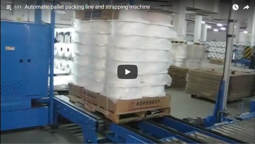
An automatic vertical pallet strapping machine secures palletized loads by driving a heavy-duty strap lance through the pallet deck voids or conveyor roller gaps, tensioning the strap around the vertical perimeter, and joining the ends via high-frequency friction welding. Structural containment depends on three engineered parameters established before commissioning: strap count and spacing, dynamic tension matching (50–5,000 N), and corner stress distribution using automatic edge protectors. Engineered for throughput rates of up to 55 pallets per hour (at two straps per pallet), our automated systems accommodate unit loads up to 1,300 mm wide and 1,800 mm high with a dry cycle time of approximately 15 seconds per strap.
Upon pallet entry via powered roller conveyor, optical position sensors trigger zero-pressure line stopping within ±5 mm repeatability. Integrated pneumatic side guides square loose layers and center the pallet relative to the arch centerline. The horizontal strap lance extends through the pallet fork voids, closing the perimeter track. High-tensile PP or PET strap feeds through the closed track at up to 3.6 m/s, retracts around the load profile, and undergoes controlled tensioning via a floating sealing head before high-frequency vibration welding seals the joint.
Table of Contents
- Planning the straps
- Vertical pallet strapping data
- Strap count and positions
- Edge protectors and tension
- One direction or cross strapping?
- Pallet and lance clearance
- Strap used per shift
- Selection checklist
- Safety
- Engineering FAQ
- Next step
- Related reading
- Sources
Planning the straps
A tensioned vertical strap maintains load integrity purely through compressive frictional coupling between stacked product layers and the pallet deck. Rigid sheet materials, wood panels, structural timber, and stacked corrugated cartons display low static friction coefficients on smooth plastic or untreated timber pallet decks (µ ≈ 0.20–0.35), making unstrapped loads susceptible to horizontal shearing under 0.8g transit deceleration (per EN 12195-1 / EUMOS 40509 standards).
The strapping recipe programmed into the PLC coordinates three variables:
- Geometric strap distribution: Spacing along the pallet length to prevent layer splaying and overhang.
- Tension threshold: Setting closed-loop tension to guarantee layer lock-down without buckling underlying cartons.
- Corner stress mitigating barriers: Inserting physical edge angle boards to prevent localized high-pressure notch tearing.
The machine stores up to 50 pre-programmed pallet strapping programs, automatically switching recipes via line barcode scanners or upstream MES communications.
Vertical pallet strapping data
| Specification Item | Engineering Metric / Standard Value |
|---|---|
| Maximum Load Height (including pallet) | 1,800 mm |
| Maximum Load Width | 1,300 mm |
| Conveyor Working Height | 300–600 mm (motorized / spindle adjustable) |
| Strap Joint Method | High-frequency friction weld (Joint efficiency ≥ 80%) |
| Joint Seal Length | 20 mm |
| Dynamic Tension Range | 50–5,000 N (stepless closed-loop electronic control) |
| Strap Feed & Retract Speed | Up to 3.6 m/s |
| Compatible Strap Types | Polypropylene (PP) or Polyester (PET) |
| Strap Dimensions | Width: 12–16 mm or 19 mm; Thickness: 0.60–1.27 mm |
| Strap Dispenser Reel Core | 406 mm (internal diameter) × 150 mm width |
| Single Strap Cycle Time | Approx. 15 s (dependent on arch dimensions and tension) |
| Automatic Edge Applicator (Option) | Top-edge feed; 50, 120, or 200 mm protector lengths |
| Strapping Head Architecture | Floating suspension (stroke: ±50 mm for balanced strap tension) |
| Lance Obstruction Detection | Integrated infrared laser beam + inductive mechanical interlock |
| Power Supply | 380 V / 400 V, 3-Phase, 50/60 Hz; 3.0 kW total rating |
| Control Hardware | Siemens S7-1200 / 1500 PLC, HMI touch panel, SEW drive motors |
Strap count and positions
The pallet indexes incrementally along the conveyor frame, halting at pre-configured strap station offsets. A baseline engineering rule places perimeter retention bands within 150–200 mm of leading and trailing edges, with intermediate strap pitches rarely exceeding 600 mm to counteract dynamic bulging.
| Load Length (mm) | Recommended Straps | Programmed Offsets from Leading Edge (mm) | Recommended Application |
|---|---|---|---|
| 1,000 | 2 | 150 and 850 | Rigid boxed freight, stable uniform cartons |
| 1,200 | 3 | 150, 600, and 1,050 | Standard EUR / GMA pallets, interlocked crates |
| 1,200 (loose sheets) | 4 | 150, 450, 750, and 1,050 | Plywood panels, insulation boards, thin veneers |
| 2,000–2,400 | 4–5 | 200, 700, 1,200, 1,700, and 2,200 | Engineered lumber, architectural extrusions |
Each added strap adds approximately 15 seconds to pallet dwell time. Line layout calculations must reconcile containment rigidity against production line takt time (e.g., 2 straps = ~30 s cycle / ~80 pallets/hr maximum; 3 straps = ~45 s cycle / ~55 pallets/hr line output).
Edge protectors and tension
Applying 3,000–5,000 N of strapping tension across a narrow 16 mm strap produces high local contact pressures exceeding 4.0 MPa. On corrugated cardboard (burst strength < 1.8 MPa) or soft pine lumber, this localized cutting action crushes outer products and causes immediate tension loss due to dimensional settling.
Optional automatic edge board applicators position heavy solidboard corner protectors (50, 120, or 200 mm lengths) beneath the strap path prior to tensioning:
- 50 mm lengths: Rigid wooden blocks, brick packs, and plastic crates where corner crushing is localized.
- 120 mm lengths: Standard RSC folding cartons, paper sacks, and light industrial panels.
- 200 mm lengths: Low-density honeycomb boxes, fragile insulation cores, and high-gloss architectural panels requiring broad surface stress distribution.
                      Applied Strap Tension (T)
                                 │
                                 ▼
         ┌───────────────────[Strap Band]───────────────────┐
         │                                                  │
         │         ┌─── Edge Board Protector ───┐           │
         │         │ (Distributes Peak Stress)  │           │
         ▼         ▼                            ▼           ▼
    [Load Corner Surface: Contact Stress reduced from >4 MPa to <0.8 MPa]
The system’s floating strapping head provides ±50 mm of lateral compliance during the tensioning phase. By floating with the strap’s retraction movement, the head equalizes strap tension across both vertical sides and the top surface. This prevents single-sided tension spikes that twist, rack, or pull stacked columns off-center.
One direction or cross strapping?
| Stability & Plant Factors | Longitudinal Straps Only | Cross Strapping (90° Intersecting) |
|---|---|---|
| Product Geometry | Long profiles, timber planks, rigid sheets | Mixed-SKU pallets, unbonded cartons, drums |
| Lateral Splaying Risk | Moderate (suppressed along length only) | Fully contained along X and Y horizontal axes |
| Cycle Overhead | Single pass: 30–45 s total dwell time | 90° rotation indexing adds 20–30 s cycle overhead |
| Machine Configuration | In-line fixed strapping arch | In-line arch with cross turntable or dual-arch cell |
Cross strapping secures pallet loads lacking internal column interlock. The pallet indexes through the vertical arch for primary transverse straps, transfers onto an integrated pneumatic 90° turntable or cross-transfer roller table, rotates, and returns through the arch for cross-tie bands.
Pallet and lance clearance
Vertical pallet strapping requires an open under-load corridor for the extending strap lance. The lance must navigate clearance windows without colliding with pallet stringers, center blocks, or bottom deck boards.
          Pallet Top Deck (Carrying Unit Load)
  ═════════════════════════════════════════════════════
     [Block]         Center Opening          [Block]
     █▀▀▀▀▀█      ┌─────────────────┐        █▀▀▀▀▀█
     █     █      │ Lance Corridor  │        █     █
     █     █      │ Min: 90 mm High │        █     █
     █▄▄▄▄▄█      └─────────────────┘        █▄▄▄▄▄█
  ─────────────────────────────────────────────────────
Conveyor Roller Surface Level- Standard EUR Pallets (1,200 × 800 mm): Minimum fork bore opening of 227 mm width × 100 mm height provides ample lance entry tolerance.
- Closed-Deck Plastic Pallets: Require pre-engineered lance pass-through tunnels or under-deck open runners.
- Conveyor Interface Gap: When strapping through pallet voids below deck level, the lance path must align with a dedicated gap between conveyor rollers (minimum clear slot: 60 mm).
All systems incorporate an optical lance monitor and motor torque sensing. If pallet positioning shifts off-center by > 15 mm or an internal board obstructs the lance path, the lance reverses instantly within 120 ms, preventing mechanical lance deformation and raising an HMI clear-path alarm.
Strap used per shift
Accurate estimation of strap consumption informs procurement volumes and reel-change intervals. The developed perimeter length per strapping loop is calculated by:
L_strap = 2 × (H_load + H_pallet + W_load) + L_overlap + L_slack
Where:
H_load: Height of unit load (m)H_pallet: Height of pallet deck structure (m)W_load: Pallet width along the strap trajectory (m)L_overlap: Sealing overlap length (standard = 0.02 m / 20 mm)L_slack: Arch radius take-up and tensioning allowance (typically 0.10 m)
For a benchmark load measuring 1,000 mm (W) × 1,200 mm (H) on a 150 mm pallet:
| Parameter Checklist | Calculation Profile | Operational Yield |
|---|---|---|
| Linear Length per Strap Loop | 2 × (1.20 + 0.15 + 1.00) + 0.02 + 0.10 | ≈ 4.82 m |
| Strap per Pallet (3 straps) | 3 × 4.82 m | ≈ 14.46 m |
| Shift Consumption (150 pallets) | 150 pallets × 14.46 m | ≈ 2,169 m (2.17 km) |
| Reel Change Interval (PET 16 × 0.8 mm) | Standard 1,500 m coil yields | ~103 pallets per reel |
| Cycle Strap Time per Pallet | 3 straps × 15 s cycle | 45 seconds line dwell |
Selection checklist
To configure an in-line strapping cell for your production envelope, verify these six technical checkpoints:
- Load Geometry: Maximum and minimum footprint dimensions (L × W × H) and gross pallet weight (kg).
- Product Rigidity & Fragility: Load deformability to establish working tension (50–5,000 N range).
- Pallet Structural Blueprint: Detailed 2D cross-section drawing showing fork cavity dimensions, runner configurations, and deck overhang.
- Edge Reinforcement: Assessment of top-layer compressive limits to determine corner protector lengths (50, 120, or 200 mm).
- Stability Specification: One-way parallel strapping versus 90° cross-strapping based on shipment transit route severity.
- Integration Boundaries: Conveyor bed height (300–600 mm), roller diameter/pitch, line communication protocol (Profibus, Profinet, or dry contacts), and target pallets per hour.
Safety
Our automated strapping systems comply with CE Machinery Directive harmonized standards:
- EN ISO 12100:2010: Comprehensive plant risk assessment and risk reduction methodologies.
- EN 415-8: Dedicated safety standard covering horizontal and vertical strapping machines.
- EN 415-10: General requirements for packaging machinery integration and modular safeguarding.
- EN 60204-1: Electrical safety, grounding continuity, and motor control circuits.
Primary hazards—including high-velocity lance travel, moving arch assemblies, and automatic sealing head mechanics—are isolated by safety fencing interlocked with dual-channel Type 4 safety switches. Conveyor infeed and outfeed openings feature Category 4 / PL e optical light curtains with active pallet blanking muting. An integrated Category 0 emergency stop circuit removes power from all SEW drives within < 100 ms upon trip.
Engineering FAQ
Q: How does high-frequency friction welding compare with metal push seals? A: Friction welding creates a homogeneous thermal molecular bond across the 20 mm strap joint without disposable metal seals. This achieves a joint efficiency of ≥ 80% of parent strap tensile strength while eliminating loose metal components that scratch sensitive products or cause tooling jams.
Q: Can the machine automatically switch tension between different pallet profiles? A: Yes. The Siemens PLC links strap tension directly to pre-set production recipes or dynamic MES line data. The system automatically adjusts closed-loop tension from delicate carton handling (e.g., 250 N) to heavy brick stacks (e.g., 4,500 N) without line stops.
Q: What is the minimum pallet opening required for the lance? A: The strap lance requires a minimum cross-sectional opening of 90 mm in height and 120 mm in width to account for pallet placement tolerances and line tracking variance (±10 mm).
Q: When should PET strap be selected over PP strap? A: Polypropylene (PP) is cost-effective for light loads and indoor storage. For heavy products (boards, bricks, metal extrusions) and long transit cycles, Polyester (PET) is required due to its higher tensile modulus, resistance to structural creep, and sustained retained tension under temperature fluctuations.
Q: What maintenance is required on the friction-weld strapping head? A: Weekly cleaning of strap residue with compressed air and routine checks of the weld tongue tooth profiles. The sealing unit incorporates modular sub-assemblies that can be fully swapped out in under 15 minutes to minimize planned maintenance downtime.
Next step
- Send your pallet drawing, unit load dimensions, and target shift volume to info@fhopepack.com.
- Our application team calculates lance clearance, layouts conveyor integration, and verifies optimal strap pitch.
- Receive a formal proposal and line layout drawing within 24 hours.
Related reading
- Vertical pallet strapping machine (product)
- Automatic turntable pallet strapping machine (product)
- Automatic pallet strapping machine
- Inline turntable pallet wrapper
- Automatic pallet strapping and wrapping machine from Shanghai, China
Sources
- FHOPE Technical Documentation: Vertical Pallet Strapping Machinery Series
- EN ISO 12100:2010 Safety of machinery — General principles for design — Risk assessment and risk reduction
- EN 415-8:2008 Safety of packaging machines — Part 8: Strapping machines
- EN 415-10:2014 Safety of packaging machines — Part 10: General requirements
- EN 60204-1:2018 Safety of machinery — Electrical equipment of machines — Part 1: General requirements
Last reviewed: 2026-10-19