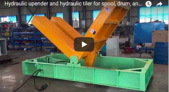
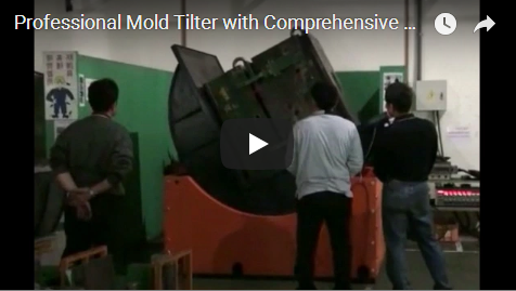
Volteadora De Moldes De 180 Grados: Operation and Applications

Summary: A heavy-duty mold rotator streamlines automated packaging lines by safely rotating industrial dies during protective packaging workflows. Operators reduce manual handling risks, cut cycle downtime, and improve throughput with precision-controlled turnover systems designed for continuous factory environments.

Should your facility tolerate frequent manual die flips? Can current turnover methods keep pace with automated packaging solutions? Will unsafe rotation practices trigger costly line stoppages? You can eliminate these risks by matching frame capacity to payload, selecting the right drive system, and verifying automatic safety locks before deployment. The following tutorial breaks down each requirement into actionable steps.

🛠️ Problem 1

Properly sizing your industrial mold rotator frame prevents structural fatigue and ensures stable turnover cycles by matching rated capacity to actual payload requirements, incorporating verified safety margins aligned with ASME B30.20 guidelines for continuous heavy component handling.

Root Cause: Static weight ratings often ignore dynamic stress—the temporary increase in load forces generated by acceleration and deceleration during rotation. Procurement teams frequently select equipment based solely on resting mold weights rather than operational envelope calculations.

Operational Impact: Undersized frames experience accelerated wear, platform misalignment, or catastrophic structural failure under peak speeds, leading to unplanned line stoppages, costly tooling damage, and potential safety violations.

Recommended Action: Calculate the true operational envelope before procurement by measuring baseline payloads and applying industry-standard safety factors rather than fixed percentages.

Step 1: Measure Base Payload

  • Record the maximum weight of every mold entering your packaging line.

  • Note the heaviest unit used in daily production cycles.

  • Add a verified safety factor (typically 15–25% above baseline) to this figure per ASME B30.20 load distribution guidelines.

Step 2: Verify Table Geometry

  • Check the maximum length, width, and height your facility rotates monthly.

  • Ensure the turning platform accommodates your largest footprint plus clamping hardware.

  • Confirm adjustable support brackets match irregular die shapes without requiring custom modifications.

Specification Requirement Operating Condition
Frame Capacity Rated capacity meets or exceeds maximum mold weight plus verified safety factor per ASME B30.20 guidelines Continuous duty under verified load distribution
Platform Dimensions Accommodates molds up to 2000mm length and 1800mm width Level floor installation with zero deflection tolerance
Clamping Range Adjusts within 300mm to 900mm vertical stroke Manual or pneumatic engagement under dry conditions

Step 3: Apply Safety Margins

  • Do not operate near maximum rated capacity for extended periods.

  • Reserve adequate frame strength for emergency braking events based on verified supplier load tests.

  • Document all weight measurements and safety factor calculations in your facility logbook.

Warning: Overloading a tilt table voids CE and UL certification markers. Structural fatigue causes unpredictable tipping during automated packaging operations.

Pass/Fail Criteria:

  • ✅ Pass: Measured payload plus verified safety margin falls below the rated capacity limit.

  • ❌ Fail: Any mold exceeds the adjusted threshold or requires custom platform modifications.

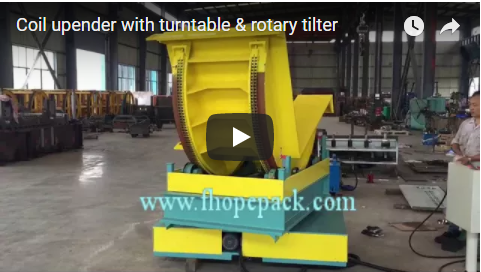
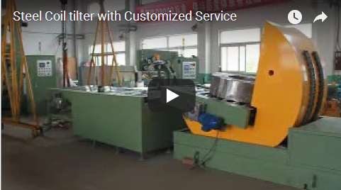
When handling alternative heavy components like metal coils, operators often compare tilt table specifications against coil upender systems. You can review rotating coil upender technology here: {d.link2}. This comparison helps you select the correct mounting geometry for your specific packaging line layout.

🏗️ Problem 2

Transitioning to electro-mechanical drive systems, which utilize high-torque motors and precision gearboxes rather than hydraulic pumps, delivers consistent turning speeds while eliminating fluid leaks and significantly reducing routine maintenance downtime across continuous factory operations.

Root Cause: Traditional hydraulic drives rely on pressurized oil to generate torque, introducing seal degradation, temperature sensitivity, and complex reservoir maintenance. Modern packaging workflows demand tighter speed regulation without the environmental overhead of fluid systems.

Operational Impact: Hydraulic fluid leaks create slip hazards and regulatory compliance burdens, while inconsistent pressure leads to variable cycle times that bottleneck automated packaging sequences and increase unplanned service calls.

Recommended Action: Transition to electric drive architectures paired with vector control—a motor management technique that independently regulates torque and speed for smooth, precise acceleration—to achieve cleaner operation and tighter speed regulation.

Step 1: Select Drive Architecture

  • Choose electromagnetic brake motors for reliable stopping capability under varying loads.

  • Verify multi-speed vector control integration with your factory PLC or automation controller.

  • Confirm independent control cabinet placement near the turning station for easy access.

Step 2: Configure Remote Interface

  • Mount the operation box at operator eye level to maintain visual contact with the mold.

  • Connect the wired control line within a five-to-ten meter length range from the host unit.

  • Test all directional inputs before loading heavy components.

Parameter Specification Verification Method
Motor Type Electromagnetic brake motor with multi-speed vector control integration Manufacturer datasheet cross-reference
Control Linkage Independent cabinet connected via 5–10 meter wired interface Signal continuity test under load
Speed Regulation Adjustable turning velocity within 0.2 to 2.0 RPM range Stopwatch measurement across three full cycles

Step 3: Calibrate Turning Range

  • Set the adjustable turning limit to stay strictly within one hundred eighty degrees.

  • Prevent product tipping by disabling over-travel software locks.

  • Record final position markers for repeatable automated packaging sequences.

Tip: Electric drive systems simplify compliance verification by eliminating hydraulic reservoirs, which streamlines CE and UL safety audits while reducing routine maintenance intervals. This lowers total cost of ownership without sacrificing torque output.

Pass/Fail Criteria:

  • ✅ Pass: Vector control maintains consistent speed across all load weights with zero slip.

  • ❌ Fail: Hydraulic fluid leaks appear at cylinder seals or pressure drops exceed five percent per cycle.

If your facility already processes ring-shaped products, you may need specialized handling equipment. Standard coil wrapping machines often pair well with tilt tables when packaging coils and molds sequentially on the same line. Explore our pallet upender specifications for integrated workflow planning: {d.link1}.

🔗 Related: Explore more solutions

📈 Problem 3

Fail-safe automatic lock mechanisms typically engage within less than 0.5 seconds during unexpected power interruptions, preventing reverse rotation and securely maintaining heavy industrial molds in place before dynamic structural stress or tipping hazards can develop.

Root Cause: Power interruptions or control signal failures can leave rotating frames unbraked, allowing momentum to carry heavy molds past safe stopping points. Legacy systems often lack redundant braking circuits required by modern safety standards.

Operational Impact: Uncontrolled swings risk operator injury, damage adjacent packaging equipment, and trigger facility-wide safety interlocks that halt entire production lines until maintenance crews reset the system.

Recommended Action: Validate fail-safe braking systems and mechanical angle limits before authorizing production use, ensuring compliance with CE and UL circuitry standards through documented testing protocols.

Step 1: Test Emergency Stop Response

  • Activate the emergency stop button during active rotation.

  • Verify typical brake engagement occurs within less than 0.5 seconds of power loss or signal interruption.

  • Confirm the system prevents reverse rotation until manual reset is performed at the control cabinet.

Step 2: Validate Turning Angle Limits

  • Set forward and reverse boundaries to exactly one hundred eighty degrees.

  • Adjust mechanical stops to match your facility floor clearance requirements.

  • Run three consecutive cyclic operations without deviation from set limits.

Safety Feature Function Compliance Standard
Automatic Lock/Stop Halts rotation immediately upon power interruption or E-stop activation CE / UL certified safety circuitry
Reverse Rotation Prevention Blocks backward movement during active turnover sequence Verified supplier conditions under test load
Pneumatic Bearing Support Maintains smooth directional control during braking events Domestic professional manufacturer sourcing

Step 3: Document Maintenance Checks

  • Inspect brake pads monthly for wear indicators.

  • Test emergency stop circuits weekly using calibrated timing equipment.

  • Replace pneumatic components only with verified replacement parts.

Warning: Bypassing automatic locks voids all safety certifications and creates severe crushing hazards during heavy component handling.

Pass/Fail Criteria:

  • ✅ Pass: Brakes engage within typical response times, reverse rotation remains blocked, and turning angles stay within calibrated limits.

  • ❌ Fail: Any delay in brake response or uncontrolled overshoot beyond the one hundred eighty-degree boundary.

🛡️ Purchase-Decision Checklist

  • [ ] Confirm maximum mold weight plus verified safety factor per ASME B30.20 guidelines matches rated frame capacity.

  • [ ] Verify platform dimensions accommodate largest die footprint plus clamping hardware.

  • [ ] Select electro-mechanical drive systems with vector control for faster cycles and cleaner operation.

  • [ ] Ensure remote controller connects via five-to-ten meter wired interface to independent cabinet.

  • [ ] Test automatic lock engagement within less than 0.5 seconds typical response time during simulated power loss.

  • [ ] Validate CE and UL certification markers on all safety circuits.

  • [ ] Schedule weekly brake inspection and monthly pneumatic bearing verification.

  • [ ] Document turning angle limits strictly at one hundred eighty degrees per cycle.

🔗 See Also: Related equipment

🛡️ Compliance Note: This equipment is designed to meet ISO and ASTM requirements. Verify specific certifications with the manufacturer before procurement.

⚙️ FAQ

What is the standard turnover speed for industrial mold tilt tables? Typical models operate between 0.2 RPM and 2.0 RPM under verified load conditions. You should adjust velocity based on maximum payload weight to prevent momentum-induced tipping during automated packaging workflows.

Can electro-mechanical drives handle molds exceeding thirty tons? Yes, provided the frame capacity exceeds your target weight by a verified safety factor aligned with ASME B30.20 guidelines. Heavy-duty electric systems use high-torque electromagnetic brake motors and reinforced gearboxes to manage extreme payloads without hydraulic fluid dependency.

How do I prevent reverse rotation during unexpected power failures? Fail-safe automatic lock mechanisms typically engage within less than 0.5 seconds when electricity cuts off or emergency stops are triggered. This feature blocks backward movement until operators manually reset the control cabinet. Always verify this function weekly using calibrated timing equipment before production shifts begin.