Executive Summary
At the exit of continuous wire drawing, patenting, or galvanizing lines, wire discharges at uninterrupted linear speeds up to 800 m/min. In contrast, downstream coil formation, mandrel extraction, indexing, and radial strapping operate on discrete cyclic timelines. If coiling cannot keep pace, line speed must be throttled; if binding tension is loose, high-tensile spring-back compromises coil geometry during material handling. An automatic steel wire coil winding and strapping system reconciles this kinematic mismatch by buffering incoming wire in a pneumatic/servo vertical accumulator, alternate-winding across dual expanding-mandrel heads, and automating through-eye strapping via servo transfer grippers. This technical guide outlines core machine stations, mechanical specifications, throughput matching calculations, and industrial safety integration.
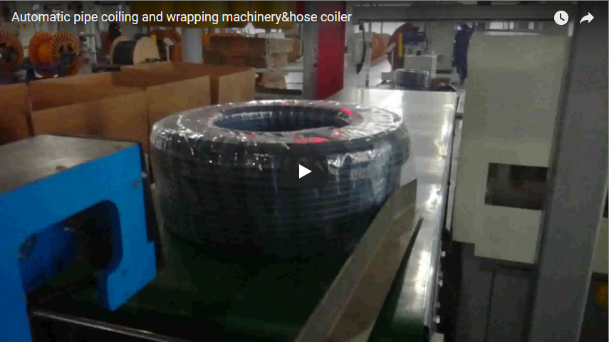
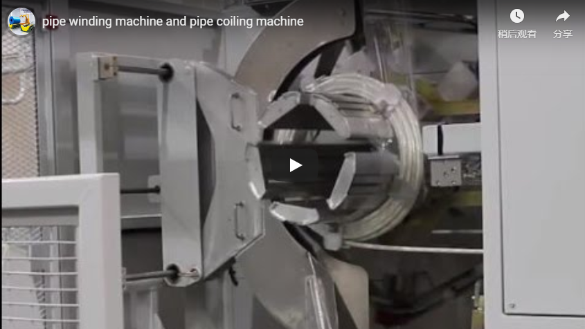
Following high-speed precision winding, a finished high-carbon wire coil rests securely on the indexing turntable between hardened vertical containment pins. An overhead gantry-mounted curved gripper with synchronized pneumatic jaws clamps the coil outer diameter to prevent turn crossing, transfers it directly to the automated strapping station, and discharges compacted units to the safety-interlocked roller conveyor.
Table of Contents
- Why Winding and Strapping Belong Together
- Machine Stations & Kinematic Sequence
- Coiler Data & Mechanical Specifications
- Coils Per Hour vs. Line Speed Calculation
- Engineering Selection Checklist
- Industrial Safety & Standard Compliance
- Engineering FAQ
- Next Step & Quotation Protocol
- Related Reading
- Sources
Why Winding and Strapping Belong Together
Cold-drawn and spring steel wires exhibit substantial residual stress and elastic memory. As soon as a coil is stripped from an unconstrained former, radial expansion causes severe loose-tailing and overlapping turns.
Manual handling to an offline strapping station inevitably distorts coil roundness, damages surface coatings, and risks fatal operator pinch injuries. By mechanically coupling the expanding-mandrel coiler directly with an automated through-the-eye strapping unit:
- Geometric Stability: The coil is gripped under controlled radial clamping force before mandrel collapse, preserving wound concentricity and uniform layer stacking.
- Continuous Line Operation: Dual-head configurations alternate seamlessly: Head A executes high-speed take-up while Head B performs automatic wire cutting, tip clamping, and coil transfer.
- Dynamic Tension Isolation: A multi-sheave vertical accumulator absorbs wire discharge during the high-speed shear and traverse switch, preventing upstream wire flutter or drawing capstan slippage.
Machine Stations & Kinematic Sequence
- Vertical Tension Accumulator: Equipped with multi-groove ceramic-coated sheaves, a low-inertia pneumatic or servo dancer maintains constant wire back-tension across speed shifts. With 5–20 m storage capacity, it provides a stable 2–4 second dynamic buffer during high-speed flying cuts and head indexed rotation at speeds between 200 and 800 m/min.
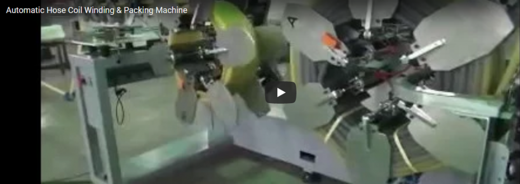
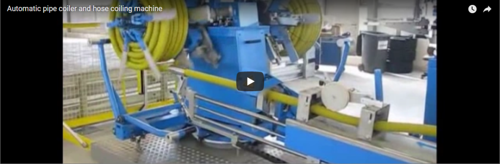
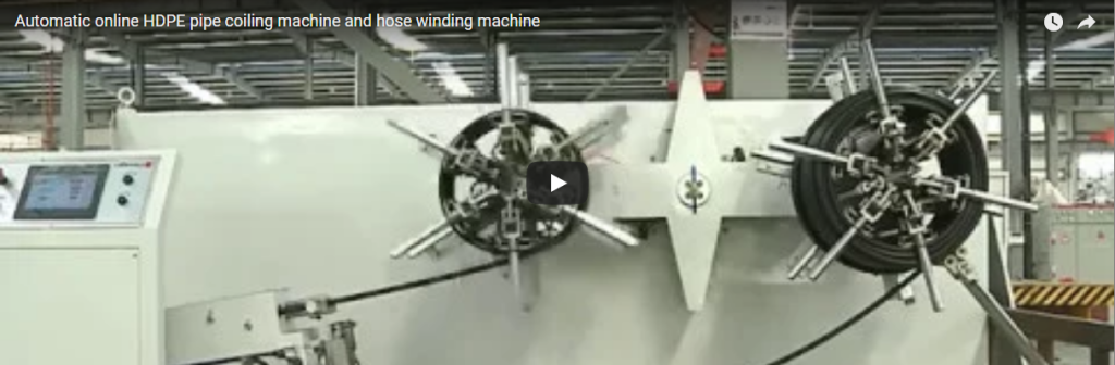
- Dual-Spindle Winding Heads: Features hydraulic collapsible mandrels and motorized traverse guides. A digital closed-loop synchronized drive matches linear spindle speed to draw-line master encoders, preventing diameter-growth over-tensioning or slack wire kinking.
- Flying Cut & Gantry Transfer: Upon reaching programmed length via pulse counter, high-speed pneumatic/hydraulic shear blades cut the wire cleanly. A dual-radius, rubber-padded overhead gantry gripper captures the coil body, lifts it off the collapsed drum, and indexes it linearly to the binding cradle.
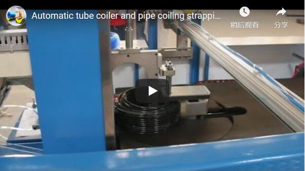
- Through-the-Eye Strapping Head: The strapping assembly indexes a radial track through the central aperture of the coil. It applies, tensions, heat-welds, or ultrasonic-seals 19 mm PP, PET, or steel strapping at 2, 3, or 4 radial indexed positions.
- Powered Outfeed & Inspection Conveyor: Strapped coils advance along driven polyurethane-sheathed roller beds directly toward integrated load-cell scales, barcode labeling systems, and downstream orbital wrapping units.
Coiler Data & Mechanical Specifications
The standard engineering parameters for the FHOPE continuous wire coiling and strapping line are outlined below:
| Technical Parameter | Specification / Performance Envelope | Engineering Details |
|---|---|---|
| Max Line Speed | 200–800 m/min | Variable frequency drive, encoder-synchronized |
| Throughput Capacity | Double-head: up to 40 coils/h Single-head: up to 20 coils/h |
Dependent on coil weight, diameter, and strap count |
| Accumulator Storage | 5–20 m wire capacity | Pneumatic dancer / linear servo tensioning |
| Tension Control | Closed-loop load cell, 24 V DC control bus | Dynamic dancer feedback, ±1.5% tension deviation |
| Centerline Height | 1,000 mm from floor | Custom height matching drawing line axis on request |
| Electrical Utility | 380 V / 440 V, 3-Phase, 50/60 Hz | PLC control: Siemens S7-1500 or Allen-Bradley |
| Pneumatic Supply | 0.6–0.8 MPa dry compressed air | Minimum flow: 450 NL/min clean, lubricated air |
| Mandrel Dimensions | Coil ID: 200–500 mm (collapsible) Coil OD: up to 900 mm |
Interchangeable segment sets available |
| Strapping Media | High-tensile PP / PET strap or mild steel strap | Through-eye binding, friction-weld or seal joint |
| Safety Integration | EN ISO 13849-1 Cat. 4 / PL e interlocks | Dual-limit overtravel switches on accumulator |
Note: Wire diameter capacity (0.8–8.0 mm), exact reel dimensions, and strap specifications are custom-engineered per plant production requirements.
Coils Per Hour vs. Line Speed Calculation
Line engineers must ensure the finishing cell cycle time is shorter than the coil fill time to eliminate line throttling:
Coils per hour needed (N_line) = (V_line × 60) ÷ L_wireWhere:
V_line= Continuous upstream line speed in meters per minute (m/min).L_wire= Total wire length per finished coil in meters (m), derived from:Coil Net Mass (kg) ÷ Unit Weight per Meter (kg/m).
Engineering Example:
- Line speed (
V_line) = 300 m/min - Wire length per coil (
L_wire) = 1,000 m N_line= (300 × 60) ÷ 1,000 = 18 coils/h
Evaluation: An 18 coils/h demand falls safely within the 20 coils/h capability of a single-head unit. However, if line speed increases to 600 m/min, required output doubles to 36 coils/h (100-second cycle per coil). Because manual or single-mandrel unloading takes 30–45 seconds, the continuous dual-head machine is mandatory to absorb the dead cycle time without slowing down the upstream capstan.
Engineering Selection Checklist
To evaluate an inline coiling and strapping project, define the following six mechanical parameters:
- Wire Metallurgy & Diameter: Carbon grade, tensile strength (MPa), yield point, bare or galvanized finish, wire gauge range (mm).
- Upstream Process Line Speed: Continuous normal running speed, ramp-up profile, and maximum burst speed (m/min).
- Coil Physical Envelope: Core inner diameter (ID), maximum outer diameter (OD), package build height/traverse width (mm), and target unit weight (kg).
- Mandrel Configuration: Single-head for intermittent batch runs vs. continuous dual-head with automated changeover.
- Strapping Specification: Polypropylene (PP), Polyester (PET), or steel strap; strap width (mm); number of radial ties (2, 3, or 4 per coil).
- Downstream Automation Integration: Requirements for inline weighing cells, automated tag application, orbital stretch wrapping, or robotic palletizing.
Industrial Safety & Standard Compliance
Wire coiling and strapping equipment must manage severe rotational kinetic energy and sharp wire ends:
- EN ISO 12100:2010: Comprehensive mechanical risk assessment and hazard elimination protocols.
- EN 415-10: Specific packaging machine safety requirements for vertical strapping and handling machinery.
- EN 60204-1: Electrical safety, enclosure IP ratings, EMC compliance, and motor protection.
- Perimeter Guarding & Interlocking: Powder-coated steel mesh fencing equipped with dual-channel coded magnetic safety switches. Entry triggers a Category 0 stop.
- Pneumatic / Hydraulic Dump Valves: Safe exhaust valves isolate mechanical actuators, discharging stored pneumatic and hydraulic pressure under emergency stop conditions.
- Accumulator Limit Safety: Redundant dual limit switches on the dancer car prevent cable rupture or mechanical binding under over-travel conditions.
Engineering FAQ
Q: Does the upstream drawing or galvanizing line need to stop during coil changeover? A: No, not with a dual-head coiling system. The flying shear and transfer guide switch incoming wire to the ready secondary mandrel within milliseconds, supported by accumulator back-tension. On single-head machines, upstream speed must be throttled or wire diverted to a drop bucket.
Q: Why invest in a dual-head architecture over a single-head machine? A: A single-head machine requires dead time for wire cutting, coil push-off, gripper clearing, and new wire clamping. A dual-head configuration eliminates this window completely: Spindle 1 coils while Spindle 2 is stripped and strapped, doubling plant production output up to 40 coils/h.
Q: How does the system prevent wire breakage during rapid acceleration? A: The dancer carriage within the accumulator uses proportional pneumatic pressure or a servo actuator to provide closed-loop tension control. A continuous encoder signal from the drawing capstan dynamically regulates coiler motor torque and spindle RPM.
Q: Can the machine handle different coil internal and external diameters? A: Yes. Mandrel leaves are interchangeable or mechanically adjustable within specific radial ranges (e.g., 200 mm to 350 mm ID), while the strapping arch and transfer gripper accommodate variable outer diameters automatically via ultrasonic sensor detection.
Next Step & Quotation Protocol
- Submit Line Specifications: Send your wire diameters, metallurgy, linear speeds, and coil dimensional prints to
info@fhopepack.com. - Kinematic & Layout Sizing: Our engineering team simulates accumulator capacity, spindle torque requirements, and strapping cycle envelopes.
- Commercial & Technical Proposal: Receive a complete mechanical layout drawing, utility demand schedule, and firm commercial quotation within 24 hours.
Related Reading
- Automatic Steel Wire Coiler Machines (Product Catalog)
- Wire Coil Compactor and Heavy Strapping Systems
- Automatic Steel Wire Coiler for Winding and Strapping (Video Demonstration)
- High-Speed Steel Wire Rewinding and Packaging Cell (Application Guide)
Sources
- FHOPE Technical Documentation: Automatic High-Speed Wire Take-Up and Strapping Lines
- International Safety Standards: EN ISO 12100:2010, EN 415-10, EN 60204-1
- Production Line Case Study: High-Speed Continuous Wire Coiling and Compacting System
Last reviewed: 2026-10-20