Executive summary A narrow coil packing line integrates radial strapping, orbital wrapping and automated gantry stacking into a single continuous packaging sequence. Slit coils enter the system in an eye-vertical (eye-to-sky) orientation, receive PET radial straps through the inner bore to eliminate telescoping, pass through an orbital ring for 100% moisture-barrier film coverage, and are then palletised by a high-precision gantry crane. This engineering guide covers the mechanics of each station, pallet layout calculations, configurable line parameters, and plant safety standards (ISO 12100 / EN 415-10) for automated slit coil handling.
Line Architecture & Sequential Station Workflow
The integrated packaging system links separate operations into a balanced conveyor flow. Rather than transferring individual slit coils across manually operated stations, the automated line synchronises transfer speeds and station dwell times across four core zones:
| Station | Mechanical Action | Engineering Function |
|---|---|---|
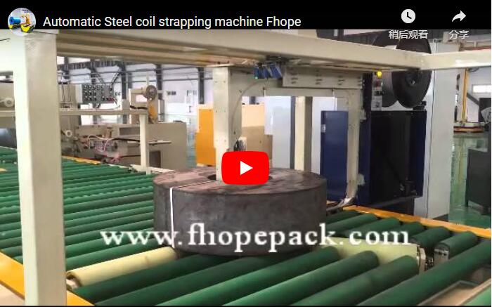
| Infeed & Strapping | Indexing roller conveyor with pneumatic centering; radial strapping head | Applies high-tension PET bands through the bore, mechanically securing slit wraps against axial sliding. |
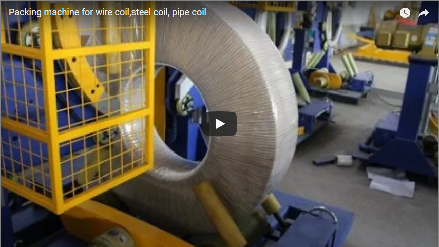
| Orbital Wrapping | High-speed orbital ring with dual-tension film dispenser carriage | Applies stretch film/VCI through the coil eye, sealing the bore, faces, and outer circumference. |
| Gantry Stacking | 2-axis/3-axis Cartesian gantry equipped with scissor-clamp or magnetic/vacuum end-effector | Lifts wrapped coils from the outfeed indexer, calculates stack offset, and deposits them onto pallets with ±1.0 mm repeatability. |
| Outfeed Staging | Heavy-duty chain/roller conveyor with integrated weighing cells | Buffers completed pallet loads for forklift or automated guided vehicle (AGV) pick-up. |
Engineering Challenges in Narrow Coil Packaging
Slit and narrow coils (typically 30–600 mm in width) behave differently from master coils during packaging:
- High Aspect Ratio & Telescoping Risk: Narrow strip coils have a small face-width relative to their outer diameter (OD). Without proper radial strapping tension, the internal strip wraps slip outward under axial vibration, creating irreparable “telescoping” damage.
- Vulnerable Edge Radii: The shear edges of steel, copper, or aluminum strip can be easily warped by excessive strap tension, or conversely, sharp strip edges can slice through packaging film if stretch wrapping tension is uncalibrated.
- High Coil Count & Stacking Stability: A single pallet load often consists of 10 to 24 narrow coils. Any geometric variation or non-parallel coil face causes lean in tall stacks, presenting tipping hazards during transport.
- Internal Bore Corrosion: Airborne humidity trapped inside the core (inner diameter) can rapidly oxidize the raw slit edges. Continuous “eye-through” stretch wrapping is necessary to seal the coil ID without manual taping.
Line Stations and Operational Mechanics
[Slit Coil Infeed]
       │
       ▼
[Station 1: Radial Strapping] ──► (Bore-through PET banding; prevents telescoping)
       │
       ▼
[Station 2: Orbital Wrapping] ──► (Eye-through stretch/VCI wrap; 6-face hermetic seal)
       │
       ▼
[Station 3: Gantry Stacker]   ──► (Pick, rotate, and palletise; layer-pad insertion)
       │
       ▼
[Station 4: Outfeed Conveyor] ──► (Full pallet buffering & scale verification)
1. Radial Strapping Station
The incoming coil is aligned by an automated V-roller or roller-lift centering mechanism. The strapping head features a curved track that shoots the strap through the open bore:
- Tension Control: Equipped with servo-driven tensioning (800–2,500 N adjustable range) to prevent edge crushing on delicate aluminum or thin-gauge steel while maintaining binding integrity.
- Joint Efficiency: Utilizes friction-welded strap sealing for PET banding (12–19 mm width), delivering a joint efficiency greater than 80% of the base strap tensile strength.
- Indexing Rotation: The coil rotates on driven support rollers to receive 2, 3, or 4 radial bands according to recipe specifications.
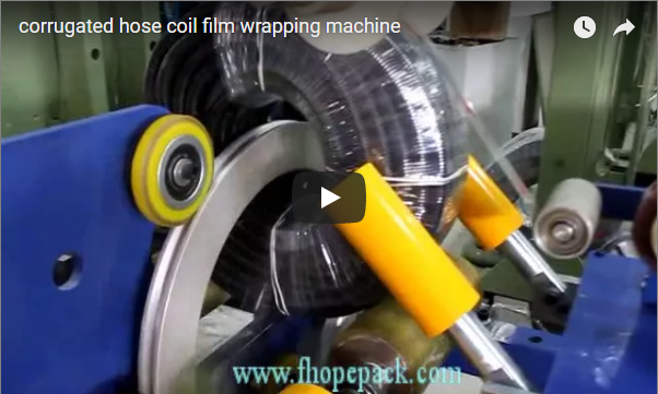
2. Orbital Wrapping Station
The coil enters the center of an orbital ring system:
- Eye-Through Coverage: A film shuttle spins through the coil bore while the coil rotates slowly around its horizontal axis. This provides complete encapsulating coverage across both lateral faces, the outside diameter (OD), and the inside diameter (ID).
- Tension & Pre-Stretch: The power pre-stretch carriage achieves elongation rates between 150% and 250%, optimizing film yield and creating elastic retention force to seal against moisture and dust.
- Film Selection: Standard lines support linear low-density polyethylene (LLDPE) stretch film, VCI anti-corrosion film, or woven composite materials for heavy transport environments.
3. Gantry Stacking Station
Once wrapped, the coil moves into the stacking envelope:
- End-Effector Tooling: Depending on strip material and surface finish, the gantry utilizes an internal expanding mechanical clamp, OD gripper jaws coated with non-marking polyurethane (PU), or vacuum lift pads.
- Palletising Logic: The PLC system tracks stack height using ultrasonic or optical distance sensors, smoothly decelerating before release to prevent shock loads.
- Interlayer Pad Handling: An auxiliary vacuum pick-up arm can be integrated to place corrugated board, timber rings, or plastic separator sheets between stacked coils.
4. Outfeed Staging Conveyor
Completed stacks rest on standard heavy-duty pallets (e.g., 1,200 × 1,200 mm). The outfeed section features powered dual-chain conveyors rated up to 4,000 kg per position, buffering up to 3 finished pallets prior to warehouse transfer.
Pallet Load Calculation
Palletizing setups balance maximum transport payload against vertical stack stability. Stack height must comply with safety ratios to prevent tip-over during rapid forklift movements.
Typical Pallet Configuration Model
       [ Stack 1 ]             [ Stack 2 ]
   ┌─────────────────┐     ┌─────────────────┐
   │    Coil #6      │     │    Coil #12     │
   ├─────────────────┤     ├─────────────────┤
   │    Coil #5      │     │    Coil #11     │
   ├─────────────────┤     ├─────────────────┤
   │  [Layer Pad]    │     │  [Layer Pad]    │
   ├─────────────────┤     ├─────────────────┤
   │    Coil #4      │     │    Coil #10     │
   ├─────────────────┤     ├─────────────────┤
   │    Coil #3      │     │    Coil #9      │
   ├─────────────────┤     ├─────────────────┤
   │    Coil #2      │     │    Coil #8      │
   ├─────────────────┤     ├─────────────────┤
   │    Coil #1      │     │    Coil #7      │
   └─────────────────┘     └─────────────────┘
   ═══════════════════════════════════════════
PALLET DECK| Calculation Parameter | Sample Metric Value | Engineering Formula / Constraint |
|---|---|---|
| Slit Coil Width | 100 mm | Specified by slitter line output |
| Weight per Coil | 150 kg | Material density × volume |
| Coils per Stack | 6 | Total Stack Height = 6 × 100 mm = 600 mm |
| Stacks per Pallet | 2 | Symmetrical placement across pallet center line |
| Total Coils per Pallet | 12 | (Coils per Stack) × (Stacks per Pallet) |
| Net Pallet Load | 1,800 kg | 12 coils × 150 kg (excluding tare weight) |
| Gross Weight | ~1,835 kg | Net Load + Pallet & Separator Tare (~35 kg) |
Engineering Stability Rules
- Aspect Ratio Limit: The total stack height divided by the coil outside diameter should be maintained at
Stack Height / Coil OD ≤ 1.5for free-standing stacks, or up to1.8when bound with intermediate layer pads. - Payload Centering: When depositing 2 stacks on a rectangular pallet, the gantry coordinates ensure the composite Center of Gravity (CoG) aligns within ±15 mm of the pallet geometric center.
Programmable Recipe Parameters
The supervisor operator or line control system selects predefined production recipes via the HMI touchscreen:
| Setting Group | Adjustable Parameters | Primary Production Driver |
|---|---|---|
| Strapping Parameters | Strap count (2, 3, or 4 radial bands); tension level (800–2,500 N); feed speed | Strip thickness, material yield strength, coil weight |
| Orbital Wrapping | Overlap ratio (30%–70%); pre-stretch ratio (100%–250%); reinforced end wraps | Export sea freight vs. short local transit protection |
| Gantry Coordination | Coils per stack (1–10); stack target coordinates; release height | Pallet deck dimensions, downstream forklift capacity |
| Pad Placement | Frequency (every coil, every 3rd coil, or top-cap only) | Surface sensitivity (bright aluminum, polished copper, automotive CR steel) |
Technical Specifications
| Parameter | Standard Range | Heavy-Duty Option |
|---|---|---|
| Coil Outside Diameter (OD) | 600–1,600 mm | Up to 2,000 mm |
| Coil Inside Diameter (ID) | 508 mm / 610 mm standard | 405 mm / 508 mm / 610 mm |
| Coil Width Range | 30–500 mm | 20–600 mm |
| Individual Coil Weight | 50–1,500 kg | Up to 3,000 kg |
| Strap Material | High-tensile PET / PP (12–19 mm) | PET (16–19 mm × 0.8–1.0 mm) |
| Wrapping Material | PE Stretch Film / VCI Film (Width: 100–250 mm) | Reinforced Woven Poly / Crepe Paper |
| Film Pre-Stretch Capacity | 150%–250% motorized pre-stretch | Dual-dispenser carriage configuration |
| Gantry Axis Stroke | X: 4,000 mm; Z: 2,500 mm (configurable) | Custom structural beam span |
| Stacking Repeatability | ±1.0 mm | ±0.5 mm with laser profiling |
| Line Cycle Time | 45–90 seconds per coil | Down to 35 seconds per coil |
| Pneumatic / Hydraulic Utility | 0.6–0.8 MPa compressed air | Integrated hydraulic pack for heavy clamps |
| Power Supply | 380V/400V/480V, 3-Phase, 50/60 Hz | As specified per client site standards |
Safety Architecture & Compliance Standards
Automated high-speed coil movement involves large mass and rotational inertia. Equipment safety complies with international manufacturing standards:
- Perimeter Guarding (ISO 14120 / ISO 13857): The entire gantry stacking envelope and strapping head zone are enclosed by steel mesh fencing (minimum height 2,000 mm) equipped with dual-channel interlocked access gates.
- Optical Presence Sensing (EN ISO 13849-1, Cat 4 / PL e): Infeed and outfeed openings are protected by muting light curtains that differentiate between advancing coil payloads and operating personnel.
- Strapping Head Lock-Out (OSHA 1910.147): Pneumatic and electrical zero-energy verification points are provided directly on the strapping sub-assembly to guarantee safe service during tape coil changes.
- Ring Drive Braking & Over-Torque Release: The orbital ring features mechanical fail-safe dynamic braking and dynamic torque feedback to instantly halt rotation if any physical resistance is encountered.
- Machinery Directives: Fully CE certified in accordance with ISO 12100:2010 (Risk Assessment) and EN 415-10:2014 (Safety of Packaging Machines).
Operational Advantages of an Integrated Line
| Advantage | Technical Mechanism | Shop Floor Impact |
|---|---|---|
| Elimination of Telescoping | Controlled-tension radial strapping applied before transfer | 0% coil rejection at customer unwinding stations |
| Total Environmental Sealing | Synchronized orbital ring rotation with 50%+ film overlap | Complete rust prevention across sea-container shipments |
| Labor Consolidation | Seamless PLC handshake from slitter exit to pallet buffer | Line operated continuously by a single supervisor |
| Zero Crane Shock Load | Gantry motion profiling with soft-landing deceleration | Prevents denting on bottom coil edges in stacks |
| Digital Order Tracking | Automatic recipe recall via central barcode / ERP integration | Fast batch changeover times under 3 minutes |
Engineering Selection Checklist
Evaluate the following factors prior to approving line layout and commissioning drawings:
- Coil Dimensional Envelope: Minimum/maximum OD, ID, and width distribution across all slit variations.
- Material Finish & Hardness: Gauge, yield strength, and surface finish (e.g., dry, oiled, galvanized, bright annealed).
- Throughput Requirements: Target cycle time per coil and planned daily output volume (coils per 8-hour shift).
- Pallet Specifications: Skid dimensions, stringer direction, maximum permissible stack height, and payload rating.
- Packaging Material Specs: PET strap core size/tensile grade; stretch film gauge (µm) and roll core specs.
- Separator Logistics: Manual placement vs. automated gantry sheet placement for layer pads.
- Factory Footprint: Center-to-center distances, bridge crane clearances, infeed/outfeed transport interface.
- Plant Automation Interface: Desired communication protocol (Profinet, Ethernet/IP, Modbus TCP) for host MES connectivity.
Engineering FAQ
Q: How does the line prevent edge deformation on narrow slit aluminum coils? A: The strapping system incorporates programmable servo tensioning down to 800 N, and the strapping guide tracks use contoured deflector shoes. In addition, the gantry clamp utilizes 15 mm thick high-grade polyurethane cushioning to ensure clamping force is evenly distributed without point loading.
Q: Can the orbital wrapper apply both stretch film and VCI paper? A: Yes. The system can be fitted with a dual-dispenser orbital ring that carries one roll of VCI anti-corrosion barrier film and one roll of standard LLDPE stretch film, applying both layers in a single orbital cycle.
Q: What is the cycle time difference between 2-strap and 4-strap configurations? A: Applying 2 radial straps with automatic 90° indexing typically takes 35–45 seconds. Applying 4 radial straps (45° or 90° intervals) increases total station cycle time to approximately 65–75 seconds per coil.
Q: How does the gantry stacker verify stack height before dropping a coil? A: The lifting carriage features optical distance-measuring laser sensors combined with drive encoder positioning. It actively confirms the top-of-stack surface before releasing the clamp, preventing dropped impacts or incorrect coil counts.
Q: What safety category applies to the perimeter guarding and access gates? A: The safety interlocks, light curtains, and emergency stop circuits comply with ISO 13849-1 Performance Level d / Level e (Category 3/4), isolating all hydraulic, pneumatic, and electric drives when safety zones are entered.
Technical Consultation & Project Layout
Line design depends on your slitter output rate, material parameters, and floor layout. You can integrate an automated packaging line with our engineering team in three steps:
- Submit Process Requirements: Provide your coil dimensional ranges (OD, ID, width, weight), pallet constraints, and target coils-per-hour to info@fhopepack.com.
- 48-Hour Technical Proposal: Receive a full mechanical specification package, preliminary cycle time study, and 2D/3D layout drawings configured to your floor space.
- On-Site Plant Survey & Integration Review: Coordinate with our commissioning engineers to inspect infeed alignment, utility drops, and AGV/forklift traffic pathways.
Related Reading
- Narrow Steel Coil Packing Line: Preventing Telescoping, Scratches & Edge Damage
- Turnstile Slit Coil Strapping Machine Architecture
- Coil Packing Line Stations: From Strapping to Stacking Integration
- Automated Slit Coil Packing Line Solutions
Sources & Design Standards
- Design baseline and automated line architecture: FHOPE Engineering Division, Technical Documentation 2026-10-10
- Visual reference: YouTube – Automatic Aluminum Coil Packaging Line with Strapping, Wrapping & Stacking
- Machinery Safety: ISO 12100:2010 – Safety of Machinery – General Principles for Design
- Packaging Machinery Specific Standard: EN 415-10:2014 – Safety of Packaging Machines, General Requirements
- Control Systems Reliability: ISO 13849-1:2015 – Safety-related Parts of Control Systems
Last technical review: 2026-10-27