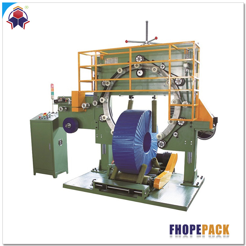
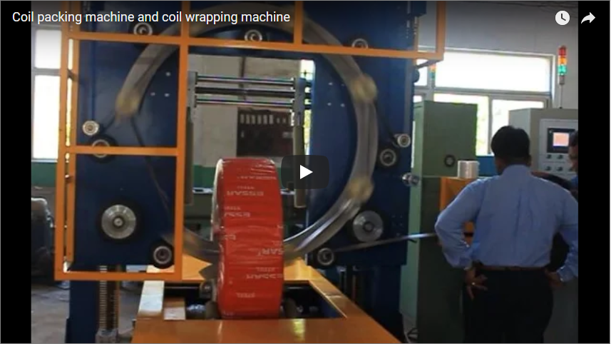
Executive summary Copper and brass strip coils exhibit high physical density (8,960 kg/m³), low yield strength, and extreme sensitivity to surface scratching and atmospheric oxidation. A standard steel coil packaging approach fails here: excessive clamping causes bore deformation, bare steel contact causes galvanic friction scratches, and open air exposure causes rapid tarnish. This engineering guide details the operation of an automated slit coil packaging line integrating a buffer turnstile discharge, high-speed radial strapping through the eye, protective wrapping, and a servo-driven vertical stacking system with integrated load-cell verification.
System Architecture & Material Flow
The automated copper strip coil packaging line coordinates material handling across five specialized mechanical zones. Rather than manual handling with cranes or C-hooks, the line uses continuous motorized rollers and dedicated handling mechanisms:
[Slitter Recoiler]
       │
       ▼
[Turnstile Buffer (Horizontal Eye)]
       │
       ▼
[90° Mechanical Tilter / Downender]
       │
       ▼ (Eye-to-Sky Transition)
[Rotary Indexing Strapping Station (Radial Strapping)]
       │
       ▼
[Orbital Eye-Through Wrapping Station]
       │
       ▼
[Vertical Gantry Stacker & Weighing Unit]
       │
       ▼
[Palletized Outfeed Conveyor]| Processing Stage | Primary Mechanical Assembly | Engineering Function |
|---|---|---|
| 1. Coil Discharge | Multi-arm Storage Turnstile | Buffers slit coils from the slitter recoiler shaft; indexes coils to the discharge push-off station without edge contact. |
| 2. Upending / Tilting | Hydraulic 90° Tilter / Downender | Transforms coil orientation from horizontal bore (eye-horizontal) to vertical bore (eye-to-sky) on non-marking PU-lined cradles. |
| 3. Radial Strapping | Rotary Table with Indexing Strapping Head | Centers the coil, rotates it at programmed intervals (90° or 120°), and feeds PET strap through the eye to secure strip tension. |
| 4. Surface Protection | Toroidal Orbital Wrapping Ring | Passes film or VCI paper rolls through the coil bore, creating a sealed 360° overlapping barrier against moisture. |
| 5. Vertical Stacking | Servo Gantry Stacker with Scissor Lift | Lifts wrapped coils using internal expanding arms or external perimeter clamps, stacking them onto pallets by weight limits. |
Why Copper Strip Coils Demand Specialized Packaging Dynamics
Processing copper (Cu-ETP, Cu-OF) and commercial brasses (CuZn37) requires packaging parameters distinct from ferrous metals:
1. Low Surface Hardness and Edge-Crimp Sensitivity
Pure copper possesses an annealed Vickers hardness as low as 40–60 HV. Any direct metal-to-metal rubbing from steel strapping, rough conveyor steel rollers, or bare metal stops causes micro-fretting and gouges that disqualify the material for fine electronic or semiconductor stamping. All load-bearing contact points in this system are shielded with cast Polyurethane (Shore A 85–90) or UHMW-PE liners.
2. High Density and Stack Imbalance
With a density of approximately 8,960 kg/m³ (14% denser than carbon steel), a pallet of narrow slit coils reaches its legal and mechanical load carrying limit well before reaching maximum volume height. Pallet packaging configurations must calculate layer stability based on weight thresholds rather than volumetric stack heights.
3. Atmospheric Tarnish and Galvanic Oxidation
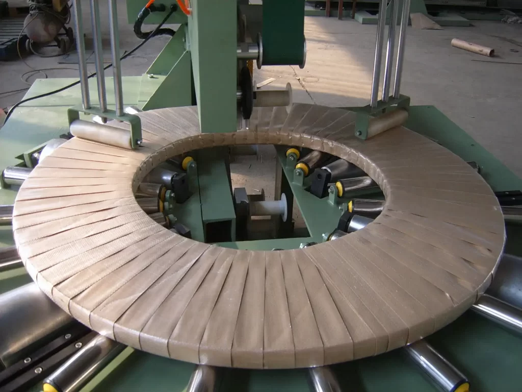
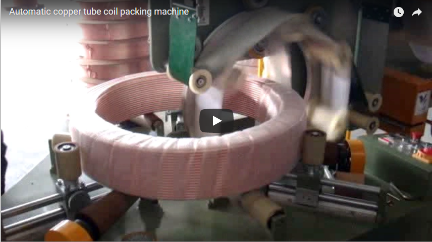
Copper tarnishes rapidly when exposed to ambient moisture, acidic industrial atmospheres, and condensation. The packaging line integrates orbital wrapping that applies stretch film or Volatile Corrosion Inhibitor (VCI) crepe paper through the coil bore, creating a hermetic seal against oxidation.
The Radial Strapping Process
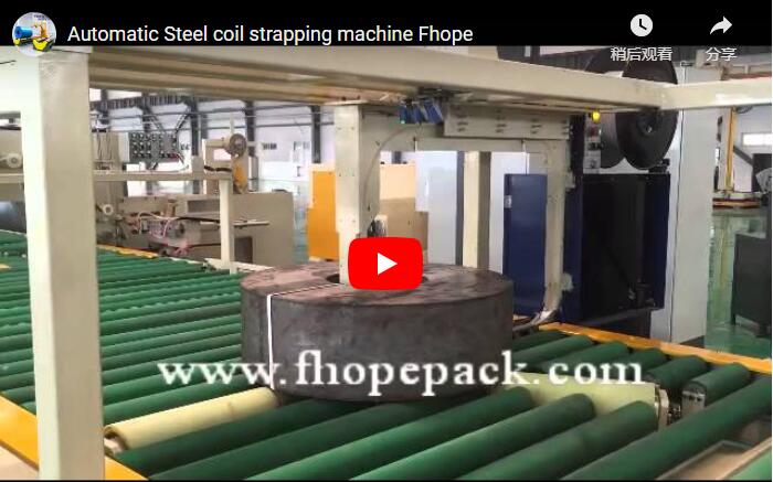
Radial strapping stabilizes individual slit coils, neutralizing residual spring tension (“clock-springing”) and preventing axial shifting (“telescoping”) during downstream handling.
       [Strapping Head]
             │
      ┌──────┴──────┐
      │  Feed Sword │ ──> Passes PET Strap Through Bore (Eye)
      └──────┬──────┘
             ▼
   [Rotary Roller Table] ──> Rotates 90° or 120° for 2 to 4 Radial Straps
Coil Centering and Turntable Indexing
The coil travels eye-to-sky along motorized rollers into the strapping station. Pneumatic centering arms clamp the outer diameter to locate the coil bore concentric with the vertical strapping track. The rotating turntable then indexes the coil through programmed angular steps:
- Narrow width coils (<50 mm): Typically receive 2 radial straps spaced at 180°.
- Medium/heavy coils (>50 mm): Receive 3 straps at 120° or 4 straps at 90°.
Tension-Controlled PET Joint Sealing
Steel banding is excluded because it cuts coil edges and risks galvanic corrosion. The automated strapping head feeds 12–16 mm PET (Polyester) strapping via a retractable strap sword passing through the eye. Strap tension is regulated via closed-loop motor torque control:
- Tension range: 500 N to 1,800 N (pre-set via HMI recipe based on copper strip thickness).
- Sealing mechanism: Friction weld or ultrasonic joint seal, achieving greater than 85% joint efficiency without metallic seals that could score adjacent coils.
Automated Vertical Stacking Mechanics
Once strapped and wrapped through the bore by the orbital wrapper, coils enter the stacking zone. The automated stacker accumulates individual coils into organized, center-aligned pallet stacks.
          [Gantry Stacker Overhead Beam]
                        │
                  [Servo Hoist]
                        │
          [Centering / Gripping Assembly]
                        ▼
             ┌─────────────────────┐
             │  Wrapped Coil (ID)  │
             └─────────────────────┘
                        │
                        ▼  (Lowering onto Pallet)
   [Layer Pad Dispenser] ──> Places Dunnage Board
                        │
                        ▼
             ┌─────────────────────┐
             │    Finished Stack   │
             └─────────────────────┘
      [Scissor Lift & Load Cell Conveyor]
Stacker Arm Kinematics
- Centering & Pickup: An overhead gantry equipped with expanding internal grippers or bottom-lifting forks matches the coil ID. Gripper fingers are faced with vulcanized polyurethane to safeguard the bore.
- Dynamic Height Sensing: A laser distance sensor detects the precise top face of the pallet or previous coil layer, executing smooth deceleration during placement.
- Automated Dunnage Placement: An auxiliary vacuum pick-up arm places corrugated disc pads or wooden spacer rings between coils when specified by the product recipe.
- Scissor Table Indexing: As coils are stacked, the receiving lift table can lower incrementally, maintaining a constant pick-and-place transfer elevation for maximum throughput.
Stack Height and Pallet Payload Mechanics
Because copper is dense, pallet loading is governed by weight capacity rather than geometric height limitations. Exceeding pallet weight ratings causes board failure and racking collapse during freight transport.
+-------------------------------------------------------+
|  Stack Calculation Principle:                        |
|                                                       |
|  1. Max Coils by Weight:                              |
|     N_stack = floor( M_payload_max ÷ M_coil )         |
|                                                       |
|  2. Total Stack Height:                               |
|     H_total = (N_stack × W_coil)                      |
|               + ( (N_stack - 1) × t_spacer )          |
|               + H_pallet                              |
+-------------------------------------------------------+
Physical Variables
M_payload_max: Certified load rating of the shipping pallet (kg)M_coil: Measured individual coil weight (kg)W_coil: Slit width / axial height of the coil (mm)t_spacer: Thickness of intermediate cardboard or wooden layer pad (mm)H_pallet: Base pallet height (mm)floor(): Mathematical integer truncation rounding down to the nearest whole integer
Engineering Worked Example
| Parameter | Value | Reference / Conditions |
|---|---|---|
Coil width (W_coil) |
120 mm | Nominal slitting width |
Measured coil weight (M_coil) |
285 kg | High-density copper strip coil |
Rated pallet payload (M_payload_max) |
2,000 kg | Standard heavy-duty timber skid |
Spacer board thickness (t_spacer) |
3.0 mm | Solid corrugated anti-slip disc |
Base pallet height (H_pallet) |
140 mm | Four-way entry heavy industrial skid |
Step 1: Determine allowable coil count:
N_stack = floor(2,000 ÷ 285) = floor(7.017) = 7 coils
Step 2: Calculate total overall stack height:
H_total = (7 × 120 mm) + ((7 - 1) × 3.0 mm) + 140 mm
H_total = 840 mm + 18 mm + 140 mm = 998 mm
Step 3: Actual payload verification:
M_actual = 7 × 285 kg = 1,995 kg (≤ 2,000 kg pallet limit — Valid)
The line’s outfeed roller conveyor incorporates an integrated industrial shear-beam load cell scale. If the measured cumulative weight exceeds the setpoint threshold, the stacker halts cycle indexing and triggers an operator alert on the HMI.
Configurable Line Parameters
The packaging line uses a central PLC database to store operating recipes across varying product specifications:
| Line Setting | Control Variable | Engineering Basis |
|---|---|---|
| Straps per Coil | 2, 3, or 4 radial straps | Selected by coil OD and slit width to counteract clock-springing. |
| Strap Tension | 500 N to 1,800 N | Modulated by strip thickness; prevents edge buckling on gauges < 0.4 mm. |
| Wrapping Overlap | 30% to 70% | Higher overlap percentage applied for maritime export packaging. |
| Wrapping Media | LLDPE Stretch Film or VCI Crepe Paper | Based on target corrosion class and shipment transit duration. |
| Stacking Pattern | Centered column or cross-spaced | Set via HMI to match client downstream de-palletizing systems. |
Technical Specifications Matrix
| Feature | Standard Configuration | Heavy-Gauge / Custom Options |
|---|---|---|
| Coil Outer Diameter (OD) | 600–1,400 mm | Up to 1,600 mm |
| Coil Inner Diameter (ID) | 508 mm standard (optional 610 mm) | 300 mm to 610 mm configurable |
| Strip Width Range | 20–400 mm | 15–600 mm |
| Maximum Coil Weight | 1,500 kg per station | 3,000 kg heavy-duty execution |
| Line Cycle Time | 45–75 seconds per coil (strapping + wrapping) | Optimized to slitter line production output |
| Strapping Material | PET strap: 12–16 mm width; 0.6–0.9 mm thickness | PP strap compatible |
| Strap Joining Method | Friction vibration weld | Joint efficiency ≥ 85% |
| Wrapping Material | PE stretch film (15–35 µm) / VCI paper roll | Reinforced woven composite fabric |
| Contact Surface Protection | Polyurethane Shore A 85–90, UHMW-PE liners | Engineered felt or brass-faced stops |
| Control Architecture | Siemens S7-1500 or Allen-Bradley PLC + Touch HMI | Full SCADA / MES line integration |
Safety Requirements & Industrial Compliance
Copper coil handling lines combine heavy payloads with high-speed automated kinematics. The system aligns with international machinery safety Directives:
| Standard / Hazard Point | Protection Mechanism | Operational Requirement |
|---|---|---|
| Turnstile & Downender Enclosure | Hard perimeter safety mesh with interlocked access doors | Automated shutdown upon gate opening (EN ISO 13849-1 Cat. 4 / PL e). |
| Strapping Head Sword Area | Optical light curtains across roller conveyor entry/exit | Automatic feed abort if foreign bodies enter the sword stroke path. |
| Stacker Drop Hazard | Pneumatic rod locks and vertical mechanical drop arrestors | Prevents stacker carriage descent during sudden pneumatic/power loss. |
| Emergency Stop Protocol | Category 0 emergency cutoffs located at each operator panel | Dual-channel safety circuit disconnects all actuator power buses. |
| Lock-out / Tag-out (LOTO) | Centralized pneumatic dump valves and padlockable isolators | Mandatory procedure compliance per OSHA 29 CFR 1910.147. |
| Machinery Safety Standards | Compliance with EN ISO 12100:2010 and EN 415-10:2014 | CE Declaration of Conformity verified for European deployments. |
Selection & Integration Checklist
Use this checklist when evaluating a packaging line layout for existing or new slitting facilities:
- Strip Dimensional Envelope: Confirm minimum/maximum OD, ID, slit strip width, and individual cut weight.
- Alloy Hardness Profile: Specify copper grade (e.g., C11000 ETP, C10200 OF) and temper condition (annealed O60 vs. hard H04) to finalize contact padding.
- Surface Finish Constraints: Mirror-buffed, tinned, or electroplated strips require specialized felt or non-marking PU linings.
- Strap Placement Requirements: Number of radial straps through the eye (2, 3, or 4 positions) per strip dimension.
- Corrosion Protection Method: Direct stretch film encapsulation vs. specialized VCI paper interleaving for export logistics.
- Pallet Specifications: Dimensions (L × W × H), maximum carrying capacity, four-way vs. two-way entry, solid deck vs. slatted skids.
- Slitter Exit Alignment: Elevation of slitter recoiler shaft and transfer car clearance to the turnstile buffer arms.
- Utilities Infrastructure: Available plant voltage, phase stability, and continuous clean dry air supply (0.5–0.7 MPa).
Engineering FAQ
Q: Why apply radial straps through the eye instead of circumferential outer diameter straps?
A: Narrow slit copper coils (widths under 200 mm) present a minimal cylindrical outer footprint. A circumferential strap applied to a narrow strip edge has high probability of slipping off during transit and can bend the fragile outer edge of the strip. Radial strapping through the eye binds the layers tightly against the inner arbor, maintaining structural roundness and preventing telescoping.
Q: How does the system prevent scratching on high-purity electrical copper coils?
A: The line eliminates all bare carbon steel contact. Conveyor rollers are vulcanized or sleeved in Shore A 85–90 polyurethane; lateral guiding arms use non-marring UHMW-PE low-friction polymer; and the stacker head uses compliant internal padding to protect the critical inner wraps of the coil.
Q: What prevents pallet overloads when coil slit widths vary?
A: The PLC program uses a dynamic recipe configuration. The stacker control calculates allowable coil count via floor(Payload Limit ÷ Actual Weight). When paired with an integrated conveyor load-cell scale, every coil stack is confirmed prior to indexing to outfeed storage.
Q: Can this line accommodate both copper strip and brass strip coils?
A: Yes. Because brass is slightly less dense than copper (approx. 8,500 kg/m³ vs. 8,960 kg/m³) but generally harder, the same line handles both alloys. The PLC recipe adjusts strapping tension and wrapping overlap dynamically based on the selected alloy ID.
Technical Project Inquiry & Quotation Support
FHOPE engineering configures custom coil strapping, wrapping, and stacking cells tailored to slitting line throughput:
- Submit Line Specifications: Email your layout drawings, slitter cycle time targets, coil size ranges, and pallet weight capacities to info@fhopepack.com.
- 48-Hour Technical Proposal: Receive a full functional equipment specification, roller center-line drawings, cycle-time analysis, and utility consumption schedules within 48 business hours.
- Engineering Site Alignment: Review interface connections between the slitter recoiler, turnstile buffer, and outfeed pallet systems with our packaging systems engineering team.
Related Systems & Reference Documentation
- Automatic Coil Packing Line Solutions
- Quality Assurance in Coil Finishing: Preventing Surface Damage
- Automated Copper Coil Packaging Line Architecture
- Kinematic Analysis of Automated Tilting and Strapping Systems
Sources & Industry Standards
- Machine specifications and functional kinematic layouts: FHOPE Systems Engineering Group.
- Copper physical properties: Standard engineering density (8,960 kg/m³) per ASTM B152 / DIN EN 13599.
- Safety and risk reduction standards: ISO 12100:2010 (Safety of machinery — General principles for design).
- Packaging machinery safety standards: EN 415-10:2014 (Safety of packaging machines — General requirements).
- Electrical and control architecture: IEC 60204-1 (Safety of machinery — Electrical equipment of machines).
Last reviewed by Engineering: 2026-10-27