Executive summary A semi-automatic horizontal orbital wrapper wraps long profiles, tubes, and extrusions in protective stretch film as they traverse a motorized rotating ring. In standard operations with manual placement, the complete handling-to-wrapping cycle runs in approximately 18 s (with 9 s of continuous spiral wrapping). Engineered for industrial integration, the S200 semi-automatic horizontal orbital wrapping machine accommodates workpieces exceeding 300 mm in length, cross-sections from 10 × 10 mm up to 200 × 200 mm (or 200 mm outer diameter), and payload weights from 10 to 100 kg.
Table of Contents
- Packaging Sequence and Motion Breakdown
- How a Semi-Automatic Orbital Wrapper Works
- Wrapping Cycle Time and Kinematic Analysis
- S200 Technical Specifications
- Takt Time Verification
- Engineering Selection Checklist
- Machine Controls, Safeguards, and Compliance
- Engineering FAQ
- Next Steps and Technical Inquiries
- Related Packaging Systems
- Standards and Engineering References
Packaging Sequence and Motion Breakdown
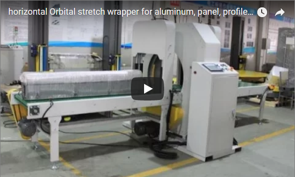
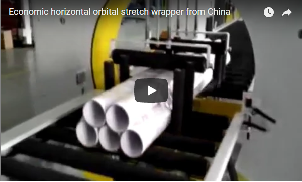
The operational unit shown features a high-rigidity fabricated steel ring housing, motorized infeed rollers on the left, an outfeed conveyor on the right, and an ergonomic operator control console located at the front-infeed station. The console integrates an emergency stop pushbutton, selector switches, cycle controls, and an industrial multi-tier indicator tower.
- 0 to 6 s (System Standby): The machine remains in ready state with the rotating orbital ring statically locked at home position. Infeed rollers are idle.
- 12 to 15 s (Manual Loading and Alignment): The operator manually transfers an aluminum structural extrusion onto the polyurethane-sleeved infeed rollers against the side guiding fence.
- 18 to 21 s (Automatic Infeed and Lead-Edge Wrap): The conveyor indexes forward to feed the leading edge into the ring clearance. The mechanical ring accelerates smoothly, capturing the leading edge and applying reinforcing end wraps.
- 24 to 27 s (Continuous Orbital Spiral Wrapping): The motorized conveyor advances the profile through the eye of the ring. Simultaneously, the orbital ring rotates at preset VFD frequency to deposit overlapping layers of stretch film along the profile body.
- 27 to 30 s (Trailing-Edge Seal and Discharge): As the tail of the workpiece exits the wrapping plane, the final wraps are completed, the film is severed, and the wrapped bundle transitions onto the outfeed conveyor.
- 33 to 39 s (Discharge and Cycle Reset): The workpiece comes to a controlled stop on the outfeed table for downstream inspection or transfer; the carriage ring stops at home position ready for the next cycle.
How a Semi-Automatic Orbital Wrapper Works
In a horizontal orbital stretch wrapping machine, the stretch film dispenser is mounted to a dynamically balanced aluminum/steel annular ring. While motorized conveyors advance the elongated profile horizontally along its primary axis (X-axis), the ring spins continuously in the vertical radial plane (Y-Z plane).
The composite vector of product advancement velocity and rotational ring velocity generates a helical film wrap. The overlap percentage is defined mathematically by the linear advance per revolution:
Advance Pitch (mm/rev) = Linear Conveyor Speed (mm/min) ÷ Ring Rotational Speed (RPM)
Overlap Ratio (%) = (1 - (Advance Pitch ÷ Film Width)) × 100%
In semi-automatic configuration, workpiece loading, batch alignment, and final offloading are managed manually by the line operator, whereas infeed conveying, variable-speed rotation, stretch tensioning, and discharge indexing are executed automatically via PLC control.
This setup offers optimum flexibility for small-to-medium batch manufacturing of aluminum extrusions, PVC profiles, copper busbars, conduit pipes, steel rods, and architectural mouldings.
| Component / Subassembly | Operational Function |
|---|---|
| Motorized Infeed Conveyor (2,000 mm) | Aligns and indexes the raw profile axially into the wrapping orbit. |
| Rotary Cast-Aluminum Ring & Carriage | Carries the film roll assembly; delivers smooth 360° orbital film coverage. |
| Mechanical Core-Brake Tensioner | Regulates stretch film release tension (10 to 45 N) to eliminate profile bending. |
| Motorized Outfeed Conveyor (2,000 mm) | Receives the wrapped profile and buffers parts for secondary packaging. |
| Ergonomic Control Console & Foot Pedal | Houses VFD controls, master emergency stop, and start/jog selector switches. |
Wrapping Cycle Time and Kinematic Analysis
The total cycle duration is governed by the length of the workpiece, the configured conveyor speed, and the required film overlap ratio.
| Packaging Phase | Video Time Window | Phase Duration | Kinematic / Operator State |
|---|---|---|---|
| Manual Part Loading | 12 to 15 s | ~3 s | Operator positions profile onto infeed bed |
| Conveyor Infeed Travel | 15 to 18 s | ~3 s | Conveyor drives profile toward ring datum |
| Orbital Spiral Wrapping | 18 to 27 s | ~9 s | Ring rotates at 80–100 RPM; conveyor runs at ~6 m/min |
| Discharge to Outfeed | 27 to 30 s | ~3 s | Wrapped profile traverses onto output station |
| Total Process Cycle | 12 to 30 s | ~18 s | Excludes idle wait and offloading |
For longer workpieces, spiral wrapping time scales linearly with length. Because the conveyor operates between 4 and 12 m/min, an elongated 3,000 mm profile passes through the wrapping plane in 15 to 45 s, depending on the overlap density requested for weather or scratch protection.
S200 Technical Specifications
| Parameter / Engineering Metric | S200 Standard Configuration |
|---|---|
| Workpiece Length Range | 300 mm to 6,000 mm (limited only by external run-out tables) |
| Allowable Cross-Sectional Envelope | 10 × 10 mm minimum up to 200 × 200 mm maximum (or 200 mm OD) |
| Payload Capacity | 10 to 100 kg per meter |
| Infeed & Outfeed Conveyors | 2,000 mm length each, motorized PU-coated / rubber-lined rollers |
| Conveyor Linear Speed | 4 to 12 m/min (Inverter / VFD adjustable) |
| Orbital Ring Rotational Speed | 20 to 120 RPM (Dynamic balanced, VFD controlled) |
| Installed Electrical Power | ~2.1 kW, AC 380 V, 3-Phase, 50/60 Hz (220 V optional) |
| Film Material Compatibility | Cast/Blown LLDPE stretch film, width: 120–200 mm, OD: ≤ 180 mm, Core ID: 50/76 mm |
| Film Thickness Range | 20 to 50 µm |
Takt Time Verification
To evaluate factory throughput against plant takt requirements, consider a target capacity of 120 wrapped bundles per hour:
Plant Takt Time = 3,600 s ÷ 120 units = 30.0 s per unit
From the engineering timing test above:
- Infeed, wrapping, and outfeed indexing consume 18.0 s.
- Available buffer for manual unloading and incoming staging:
30.0 s - 18.0 s = 12.0 s.
Because an operator typically requires 5 to 8 s to transfer bundled profiles, the S200 comfortably supports a continuous 120 parts/hour takt for 2-meter profiles. For long products (> 4 m), calculate cycle time by dividing workpiece length by infeed velocity, and adjust conveyor speeds to maintain production line equilibrium.
Engineering Selection Checklist
Before specifying an orbital wrapping configuration, mechanical engineers and plant managers should audit the following physical parameters:
- Cross-Sectional Enclosure: Confirm profile diagonal
√(Width² + Height²) ≤ 280 mmto preserve dynamic clearance inside the ring inner diameter. - Minimum Length Support: Ensure workpiece length exceeds 300 mm to span between the infeed and outfeed roller bridging gaps.
- Surface Sensitivity: Specify rubber-coated rollers, brush conveyors, or pneumatic top hold-down wheels for mirror-finish aluminum or painted profiles.
- Film Barrier Requirement: Determine single-layer dust protection (30% overlap) versus multi-layer marine/export moisture barrier (60%–80% overlap).
- Shop Floor Footprint: Allocate minimum linear footprint of 4,800 mm (2,000 mm infeed + 800 mm chassis + 2,000 mm outfeed) plus safe perimeter clearance.
- Automation Additions: Evaluate optional pneumatic cut-and-clamp units, automated side guide centering, or gravity return conveyors.
Machine Controls, Safeguards, and Compliance
The primary hazard zones on an orbital wrapper are the rotating annular ring perimeter, the film carriage rotation trajectory, and conveyor infeed/outfeed pinch points.
- Safe Operating Protocol: Operators must only load and unload while the machine is at rest or during non-interfering conveying phases. Hands must never enter the rotating ring enclosure during operation.
- Lockout/Tagout (LOTO): Comply with OSHA standard 29 CFR 1910.147. Isolate pneumatic and electrical power sources prior to film threading, roller cleaning, or maintenance.
- Harmonized Standards Compliance:
- ISO 12100:2010: Risk assessment and risk reduction design methodology.
- EN 415-10:2014: Safety requirements for pallet wrapping and orbital packaging machinery.
- IEC 60204-1: Electrical safety, category 0/1 emergency stop circuits, and protective equipotential bonding.
Engineering FAQ
Q: What is the exact cycle time per profile on the S200? A: On a standard 1.5 to 2.0 m profile, the pure spiral wrapping stage takes approximately 9 s, with total machine transit time averaging 18 s. Total door-to-door takt including manual loading/offloading is typically 24 to 28 s.
Q: What geometric limits apply to the S200 wrapping aperture? A: The machine handles parts with maximum cross-sectional dimensions of 200 × 200 mm or circular diameters up to 200 mm. Minimum product length is 300 mm, with standard unit weights between 10 kg and 100 kg.
Q: What operational elements make this machine “semi-automatic”? A: Workpiece loading, side positioning, and removal are performed manually by line operators. The dynamic functions—including variable-speed conveyor drive, rotary ring orbital wrapping, constant-tension film feed, and index stop—are executed automatically by the PLC system.
Next Steps and Technical Inquiries
We engineer and size horizontal orbital packaging machinery tailored to your product profiles and throughput targets:
- Submit Product Envelope: Send your layout drawings, profile dimensions (W × H × L), product weights, and target parts-per-hour to info@fhopepack.com.
- Proposal & Kinematic Simulation (Within 48 Hours): Receive a customized proposal including ring sizing, speed calculations, overlap simulations, and conveyor integration layouts.
- Engineering Consultation: Review layout footprints, electrical voltage options (220V/380V/480V), and surface-protection roller selections with our technical team.
Related Packaging Systems
- Semi-Automatic Horizontal Orbital Wrapper S200
- Semi-Automatic Horizontal Film Wrapping Machine S300
- Coil Wrapping Machine with Taping and Label Printer
- Razor Wire and Barbed Wire Packaging Machine
Standards and Engineering References
- Equipment Specifications: Fhopepack S200 Semi-Automatic Horizontal Orbital Wrapper
- Machinery Safety Standards: ISO 12100:2010 Safety of Machinery
- Packaging Machinery Specific Safety: EN 415-10:2014 Packaging Machines Safety
- Video Verification & Motion Tracking: S200 Operational Demonstration Sequence (3-second discrete interval capture)
Last reviewed: 2026-10-05