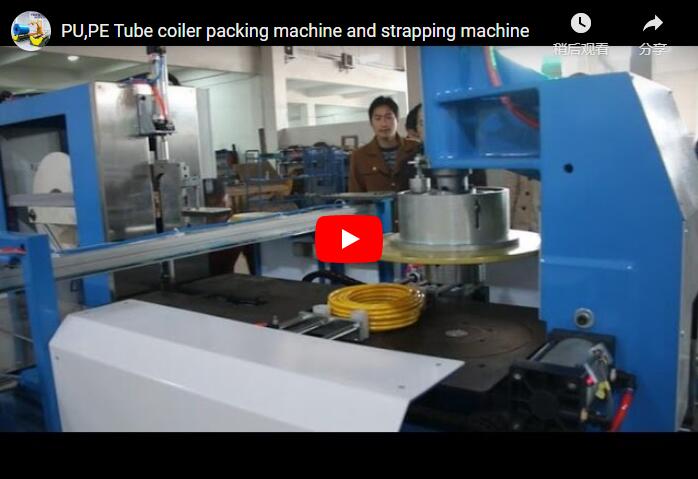
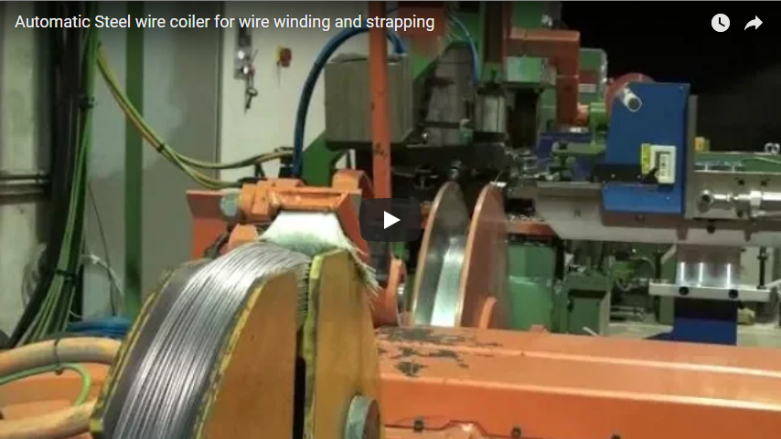
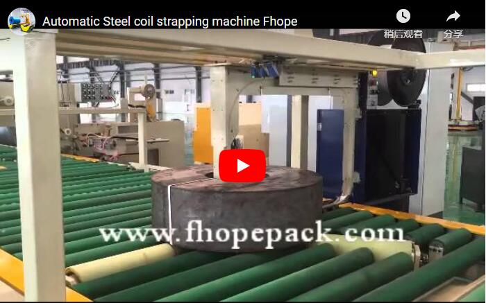
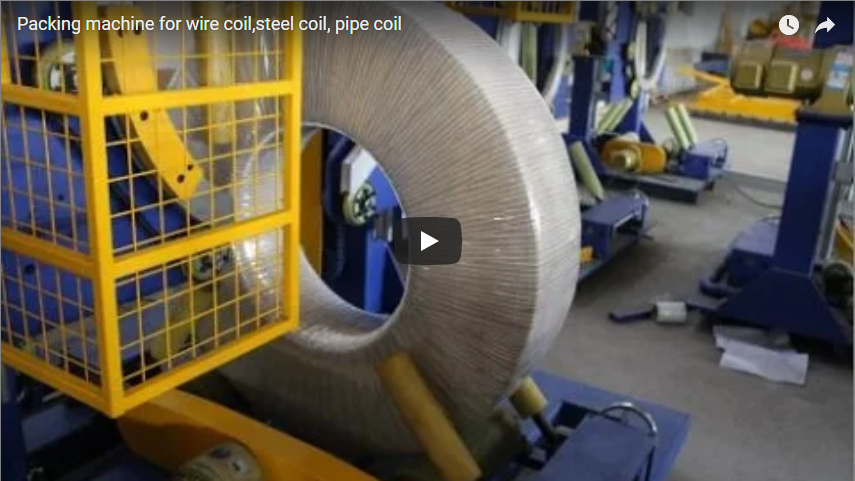
Executive summary High-purity copper and brass slit coils are exceptionally vulnerable to surface scratching, edge burr deformation, and telescoping during post-slitting handling. This integrated automated packaging line transitions pancake coils from eye-horizontal (spindle-wound) to eye-to-sky (flat) orientation via a dual-hydraulic cushioned upender, secures the core pack through servo-tensioned radial PET strapping, encapsulates the profile with high-precision orbital eye-through stretch wrapping, and completes pallet stacking with a non-marking mechanical gantry grab. Every metal-to-metal contact point is isolated by 90–95 Shore A polyurethane (PU) and engineered polymers to guarantee zero-defect surface preservation.
Why Copper Requires a Special Approach
Copper and refined copper alloys (such as C11000 ETP, C10200 OFC, and precision phosphor bronze) feature high density (approx. 8.94 g/cm³) coupled with low surface hardness (often 40–65 HV in annealed states). In coil processing, this metallurgical profile presents severe mechanical handling vulnerabilities:
- Surface Sensitivity: Minor frictional sliding between bare metal and conveyor steel generates irreversible micro-abrasions, surface oxidation, and work-hardening scratches that cause immediate rejection in electrical busbar, lead frame, and transformer winding applications.
- Edge Telescoping and Flange Crushing: Narrow slit pancake coils possess low axial stability. Excessive or uneven axial loads shift internal coil wraps out of alignment (telescoping), while uncontrolled radial strap tensions pinch and deform outer edge geometries.
- Contact Stress Concentration: Standard steel coil lines rely on knurled steel rollers and high-tension hydraulic clamps. When applied to soft copper, these mechanisms generate point-loading stresses exceeding the yield point of the metal, causing deep indentations.
Eliminating these risks requires purpose-engineered kinematics: continuous polyurethane shielding, cushioned hydraulic acceleration/deceleration curves, and calibrated, servo-governed securing mechanisms.
What the Line Does — Step by Step
The packaging sequence transitions slit copper coils from individual vertical slitter unloading arms through to secured, shipping-ready pallet stacks through four fully automated stations.
[Slitter Turnstile / Car]
         │ (Eye-Horizontal)
         ▼
[1. 90° Hydraulic Cushioned Upender]
         │ (Polyurethane contact, proportional decelerated tilt)
         ▼ (Eye-to-Sky)
[2. Radial Eye-Through Strapping Station]
         │ (Cushioned index table, 400–1200 N regulated PET banding)
         ▼
[3. Orbital Eye-Through Wrapping System]
         │ (VCI + Stretch film composite shuttle ring)
         ▼
[4. Overhead Gantry Stacking & Palletizing]
         │ (Internal-bore expanding jaws / cushioned O.D. pads)
         ▼
[Finished Pallet Staging Conveyor]
1. Upending: 90° Dynamic Tilt from Eye-Horizontal to Flat
Coils arrive eye-horizontal from the slitter turnstile. The 90° tilting cradle uses an electro-hydraulic proportional system featuring dual-cylinder synchronization.
- Both the horizontal receiving arm and the tilting backplate are lined with 15–20 mm high-density cast polyurethane (90–95 Shore A) to isolate coil outer diameters and side faces.
- The motion profile executes an S-curve acceleration and deceleration sequence, eliminating impact shock at the 85°–90° handover point and transferring the coil smoothly to the roller table in an eye-to-sky (flat) orientation without edge tipping.
2. Radial Strapping: Precision Through-the-Eye Tensioning
Once seated flat on the conveyor, the coil indexes to the strapping station. Unlike bulk carbon steel coils that accept raw circumferential outer-diameter banding, pancake copper coils require radial strapping through the central bore to bind the individual windings against axial displacement.
- An automated indexing turntable rotates the coil beneath a traversing strap track that shoots PET strapping through the center eye.
- The strap tensioning head is governed by an adjustable servo-pneumatic feedback loop, operating between 400 N and 1200 N. This ensures structural package tightness while remaining safely below the compressive threshold that causes coil edge curl. Edge-protection feed inserts can be integrated automatically for ultra-thin foil applications.
3. Eye-Through Orbital Wrapping
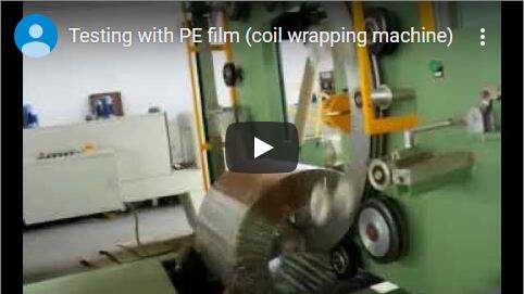
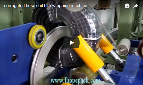
The coil transfers into the orbital stretch wrapping station, where a high-speed rotational shuttle ring travels continuously through the coil eye and around the outer circumference.
- The shuttle applies a continuous spiral barrier of stretch film, VCI anti-corrosion film, or woven polypropylene tape.
- Because the wrapping ring orbits without contacting the coil, mechanical contact is limited strictly to the driven polyurethane-sleeved support rollers that rotate the coil about its central vertical axis.
- Film pre-stretch is mechanically or electronically maintained between 150% and 250%, generating high elastic retention around the core while shielding the bare copper from atmospheric moisture and oxidation.
4. Gantry Stacking and Palletizing
The wrapped coil moves to the pick-and-place exit station. A heavy-duty overhead gantry system lowers an automated pick head equipped with polyurethane-coated internal expanding segments or external perimeter gripping clamps.
- The gantry centers over the coil eye, engages the load with zero relative sliding, and lifts vertically under vector-inverter hoist control.
- Coils are transferred and gently stacked onto wooden shipping pallets according to pre-programmed layer recipes (e.g., 3 to 6 coils per skid) with soft-touch landing routines that avoid compressive impact.
Scratch Protection — Critical Quality Checkpoints
To ensure zero surface degradation, commissioning protocols mandate systematic verification at each transfer interface:
| Equipment Station | Critical Inspection Focus | Engineering Defense Mechanism |
|---|---|---|
| Upender Cradle & Faceplate | Face marking, edge point-loading | 15–20 mm cast 90–95 Shore A PU lining; proportional hydraulic soft-landing valves |
| Roller Conveyor System | Scuffing, relative slip during transfer | High-grade vulcanized PU roller sleeves; VFD-synchronized motorized rollers |
| Through-Eye Strapping Head | Edge notch cutting, strap biting | 12–16 mm PET strap (smooth profile); servo-regulated tensioning (400–1200 N) |
| Orbital Wrapping Carriage | Machine collision, uneven pre-stretch | Dynamic optical coil-centering; non-contact revolving ring; constant-torque film carriage |
| Gantry Crane Gripper | Bore scoring, drop impact on pallet | UHMW-PE bore locating shoes; pneumatic soft-touch descent sensors; smooth VFD ramp-down |
For ultra-sensitive bright-annealed copper and oxygen-free grades (OFC > 99.99%), non-marking neoprene roller sleeves and clean-room-compatible VCI composite wrapping media are specified to prevent chemical staining and mechanical abrasion.
Line Throughput and Cycle Time Model
Overall throughput is governed by the pacing workstation (the slowest individual process cycle) plus inter-station transfer times:
| Station Action | Unit Cycle Time | Engineering Operational Parameters |
|---|---|---|
| Coil Infeed & 90° Upending | 40 s | Proportional hydraulic tilt including soft-stop settlement |
| Conveyor Transfer & Positioning | 12 s | Synchronized soft-start roll index (0.2 m/s) |
| Radial Strapping (3 Straps) | 36 s | 3 × 12 s per radial strap cycle (including 120° coil indexing) |
| Orbital Wrapping (60% Overlap) | 45 s | Dual-layer wrap at 60 RPM ring speed |
| Gantry Pick, Travel & Stack | 35 s | Full traverse cycle with soft-touch pallet landing |
| Pacing Workstation Cycle | 45 s | Orbital wrapping operation sets single-station baseline |
Effective Throughput Analysis: With integrated buffering zones between the upender, strapping unit, and wrapper, inter-station operations run concurrently. Accounting for mechanical handovers and indexing verification, the continuous line pacing achieves 50 to 65 coils per hour, maintaining consistent production while respecting the physical speed limits required for soft-metal surface protection.
Technical Specifications
| Parameter | Operational Range / Specification |
|---|---|
| Coil Payload Weight | 500 – 5,000 kg |
| Coil Outer Diameter (OD) | 600 – 1,800 mm |
| Coil Inner Diameter (ID) | 300, 400, 508, 610 mm (Standard Mandrel Sizes) |
| Slit Coil Width (Height when flat) | 50 – 500 mm (Pancake / Strip Coils) |
| Strapping Material | Machine-grade PET strap (Width: 12 – 16 mm; Thickness: 0.6 – 0.8 mm) |
| Packaging Films | VCI Film, LLDPE Stretch Film, PE Woven Fabric (Width: 100 – 250 mm) |
| Conveyor Surface Hardness | Polyurethane / Rubber vulcanized coating (90 – 95 Shore A) |
| Control Architecture | Siemens S7-1500 / Allen-Bradley GuardLogix PLC; Pro-face / Siemens HMI |
| Pneumatic / Hydraulic Supply | 0.6 – 0.8 MPa (Clean dry air); 14 – 18 MPa (Proportional hydraulic pack) |
| Power Supply | 380V / 415V / 480V, 50/60 Hz, 3-Phase (Customized per country) |
Selection Checklist
Prior to finalized mechanical layout and quotation, ensure the following engineering parameters are confirmed:
- Coil Dimensional Envelope: Minimum/maximum OD, standard ID, width range, and individual coil weight.
- Metallurgical State & Finish: Alloy designation, annealing state (soft vs. hard), and specific surface requirements (e.g., mirror finish, tinned, bare bright).
- Required Throughput: Target coils per hour based on slitting shear output capacity.
- Strapping Configuration: Number of radial ties required (typically 3 or 4 straps at 120° or 90° intervals).
- Packaging Layer Recipe: Stretch film only, VCI film inner layer, or reinforced external woven wrap for overseas container shipping.
- Stacking Specifications: Pallet dimensions, maximum stack height, target stack weight, and pallet discharge conveyor orientation.
- Factory Layout & Constraints: Linear inline orientation versus 90° L-shape configuration relative to the slitter bay exit.
Safety Standards & Compliance
Automated heavy-coil handling operations must prioritize operator protection alongside product integrity:
- ISO 12100:2010: Comprehensive risk assessment integrated into machine framing, hydraulic rupture drop-stops, and kinematic clearance design.
- EN 415-10:2014: Dedicated safety standard covering wrapping, strapping, and integrated material handling packaging machinery.
- Zone Isolation: Cat 4 / PL e safety light curtains and interlocked perimeter safety fencing guarding the upender rotation path, orbital ring, and gantry envelope.
- Energy Isolation: Fully lockable Lockout/Tagout (OSHA LOTO compliant) electrical circuit breakers and residual-pressure hydraulic bleeding valves for safe system maintenance.
Engineering FAQ
Why can conventional steel coil strapping heads not be used directly on copper strip?
Standard steel coil strapping equipment relies on high strap tensioning (often >2,500 N) and toothed friction weld grippers designed for stiff carbon steel. On soft copper coils, these heads cause deep corner indentation, crimp the edge laminations, and cause burr damage that disrupts high-speed stamping operations downstream. Our line incorporates low-inertia, servo-regulated tensioning heads with radiused feed chutes and smooth-joint friction welding calibrated specifically for copper coils.
What mechanism prevents coil telescoping during 90° upending?
Coil telescoping occurs when axial inertia overcomes inter-wrap friction during tilting. Our upender design mitigates this using a synchronized hydraulic tilt motion with proportional flow deceleration. The coil sits flush against a polyurethane-padded baseplate, and the rotation pivot point is engineered to keep the net gravity vector shifting smoothly into the supporting corner pocket, arresting axial shear movement.
Can the line handle both single pancake coils and stacked master coils?
Yes. The strapping head and orbital wrapping carriage feature optical laser height detection that continuously calculates workpiece profiles. Whether receiving an individual 60 mm wide slit pancake coil or a pre-stacked 400 mm wide bundle, the system automatically adjusts wrap carriage travel strokes and strapping feeder positions through predefined recipe codes in the PLC.
How is condensation and surface tarnish prevented during sea transit?
For long-distance maritime export, bare copper is prone to oxidation and humidity staining. The orbital wrapping shuttle can be configured with dual film dispensers: an inner reel applying active volatile corrosion inhibitor (VCI) film directly to the bare metal, followed by an outer layer of high-tension LLDPE stretch film. This dual-barrier seal creates a tight moisture-proof micro-environment that eliminates the need for messy rust-preventative dipping oils.
Next Steps
To evaluate an integrated copper coil handling, strapping, and orbital packaging line engineered to your bay layout:
- Submit Your Application Data: Forward your coil dimensions (OD, ID, width, mass), hourly volume requirements, and bay footprint to info@fhopepack.com.
- Receive 3D Layout & Technical Specification within 48 Hours: Our mechanical project team will deliver a station-by-station line proposal with cycle time simulation, layout drawings, and surface-protection details.
- Engineering Site Alignment: Schedule an on-site or virtual engineering review to verify foundation loading, cycle integration with slitting turnstiles, and electrical busbar interfaces.
Related Reading
- Slit Coil Tilting, Eye-Through Wrapping and Stacking Line
- Kinematic and Structural Analysis of Hydraulic Tilting Mechanisms for Delicate Strip Coils
- Automatic Copper Strip Coil Packaging Systems — Equipment Series
Engineering Documentation & Reference Sources
- Machine Design & Application: FHOPE Systems Engineering Technical Group
- Video Demonstration: Automatic Copper Coil Packaging Line Showcase
- Functional Cycle Calculations: FHOPE Engineering Commissioning Time-Study Standards
- Regulatory Safety Compliance: ISO 12100:2010 (Safety of Machinery – General Principles); EN 415-10:2014 (Safety of Packaging Machines – Part 10: General Requirements)
- Project Proposal Turnaround: Standard OEM 48-Hour Engineering Review Protocol