Executive Summary
The FPCA series is a semi-automatic orbital wrapper for light-to-medium wire coils, cable bundles and flexible tubing. Three things have to be set together: roller spacing, carriage brake tension, and the ratio between ring speed and coil advance. This guide covers those settings, the film thread-up, and the cycle for the FPCA-200 and FPCA-300.
What the FPCA ring does
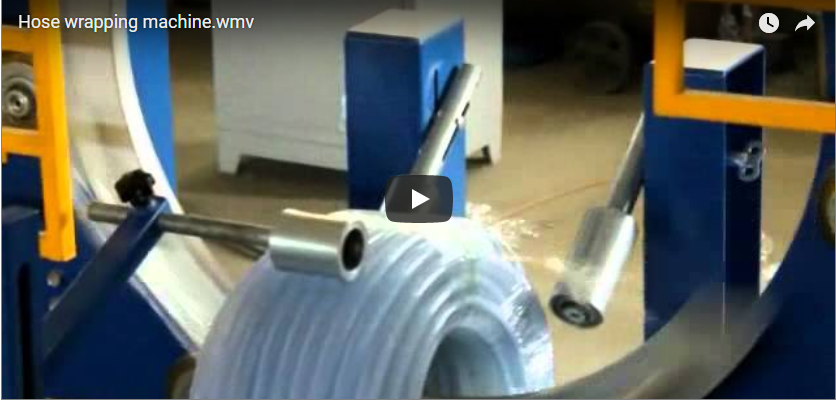
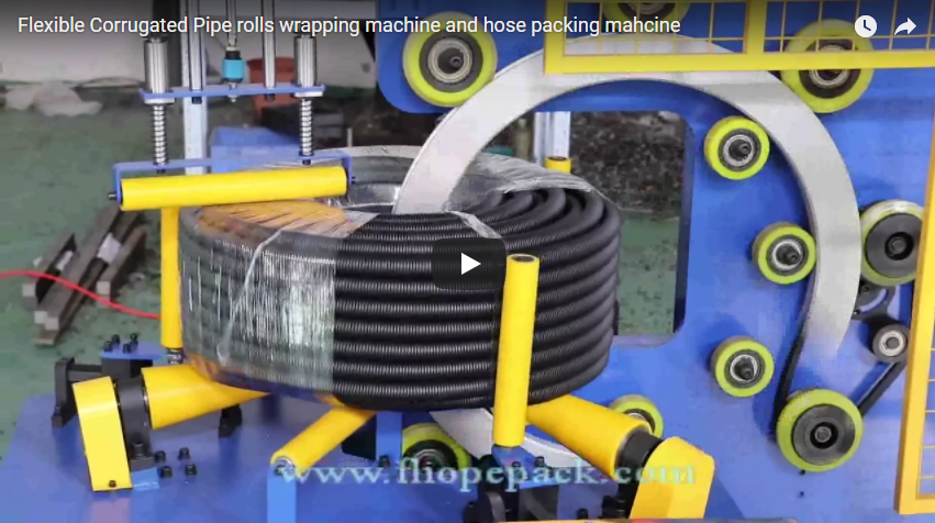
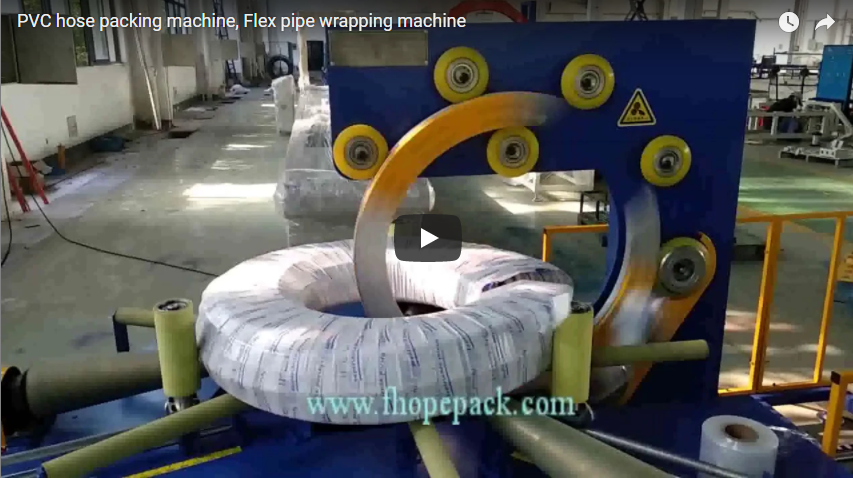
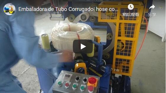
The coil stands vertically on two motorised lower rollers; the rollers turn it about its own axis while the ring carries the film carriage through the open centre.
Ring kinematics in plain numbers
The density of the protective packaging depends on the film overlap ratio. On the FPCA system, the orbital ring rotation speed determines the time required per wrap, while the surface linear speed of the support rollers determines how far the coil advances along its outer circumference between consecutive wraps. This linear advance is the wrap pitch.
The kinematic relationship is defined by:
Pitch = W_film × (1 - Overlap_ratio)
Where:
Pitchis the circumferential advance per ring revolution along the outer diameter (mm).W_filmis the effective width of the stretch film web (mm).Overlap_ratiois the target overlap fraction (e.g., 0.30 for 30%, 0.60 for 60%).
When running standard 90 mm wide film on an FPCA-300 station (which supports continuously variable overlap between 10% and 90%), the mechanical pitch is set according to protective requirements:
- 30% Overlap (General dust protection and fast handling):
Pitch = 90 mm × (1 - 0.30) = 63 mmThe roller drive rotates the coil 63 mm along its outer circumference for each 360° rotation of the orbital ring. - 60% Overlap (Heavy-duty puncture resistance and tight bundling):
Pitch = 90 mm × (1 - 0.60) = 36 mmThe roller drive speed is decreased relative to ring speed, advancing the coil only 36 mm per ring cycle.
Because the inner diameter (ID) circumference is smaller than the outer diameter (OD), film wraps naturally accumulate closer together inside the eye. Packaging technicians must always calculate and set the advance pitch based on the outer diameter to ensure the minimum required coverage across the entire exterior.
Setup: film, thread-up and overlap
Proper film installation ensures uniform stretch without tearing the web or crushing delicate plastic tubing.
[Film Spindle] —> [Tension Core Brake] —> [Guide Roller 1] —> [Guide Roller 2] —> [Coil Lead]
Film Loading and Thread-up Steps
- Mount Film Roll: Place a film roll with core inner diameter ID 50 mm (or standard 76 mm) and outer diameter OD 150–450 mm onto the carriage mandrel. Lock the knurled retaining cap firmly.
- Web Routing: Thread the film web through the polished dual guide rollers. Ensure the cling side faces the product surface.
- Brake setting: adjust the friction nut on the carriage spindle by trial — pull a length by hand and check the film necks down smoothly without jerking or stalling on your coil.
- Anchor Film Lead: Pull approximately 400 mm of film leader and secure it into the inner eye or clamp it beneath the first product turn.
- Dry Run Verification: Cycle the orbital ring for one slow, manual jog rotation. Confirm the film dispenses smoothly over the outer shoulders without twisting, tearing, or riding off the carriage guide pins.
Changeover Checkpoint Matrix (3-Step Rule)
When changing product coil dimensions or film stock, complete this verification before clearing the line:
| Verification Step | Target Inspection Point | Correction Method |
|---|---|---|
| 1. Film Width | Measure loaded film width (typically 90–120 mm) | Match dispenser mandrel collars to avoid web walk |
| 2. Overlap Setting | Calculate required pitch for target overlap | Adjust roller drive potentiometer on operator panel |
| 3. Ring Speed | Confirm ring inverter RPM matches coil rigidity | Lower ring acceleration ramp if lightweight coils shift |
Cycle time for small and mid coils
Cycle time is ring speed plus handling. Floor to floor:
t_total = (N_wraps × 60 / Ring_speed) + t_handling
Where:
N_wrapsis the total number of ring revolutions needed for complete circumferential coverage.Ring_speedis the inverter frequency setting in revolutions per minute (r/min).t_handlingis loading, film lead tuck, cut-off and unloading time — measured on your floor for your operator.
The cycle is three phases: load and tuck the film lead, run the wrap count, cut and unload. Only the middle phase is timed by the ring; the other two are yours to measure.
Two sizes:
- 8 wraps on FPCA-200: at its stated 20–30 s/pcs, the ring phase is 8 × 60 ÷ ring speed and the rest of the 20–30 s is load and handling.
- 12 wraps on FPCA-300: inside its 20–38 s/pcs window, 12 wraps close larger cable coils fully.
Engineering Note on Kinematics: The longer cycle time required for larger coils is a geometric consequence of increased circumference requiring more wraps (N_wraps = 12 vs. 8), not a reduction in ring angular velocity. The ring maintains its set rotational speed, ensuring consistent wrap tension regardless of package diameter.
Two models side by side
The FPCA series offers two primary chassis configurations to handle distinct coil dimensions and production throughputs:
| Engineering Specification | FPCA-200 | FPCA-300 |
|---|---|---|
| Primary Coil Application | Small wire, braided hose, light cables | Heavy cable bundles, flexible conduit, hose |
| Wrapping Cycle Duration | 20–30 s/pcs | 20–38 s/pcs |
| Film Overlap Range | 20%–80% (Continuously variable) | 10%–90% (Continuously variable) |
| Drive System Control | Dual VFD frequency control | Dual VFD frequency control |
| Standard Electrical Supply | AC 220V/380V (50/60 Hz) | AC 380V/60Hz (or customer specified) |
| Compatible Film Types | LLDPE stretch film, PE | LLDPE, PE, VCI anti-corrosion, woven tape |
| Compatible Film Dimensions | ID 50 mm / 76 mm; OD ≤ 250 mm | ID 50 mm / 76 mm; OD 150–450 mm; width 90–120 mm |
| Ring Homing Mechanism | Inductive proximity sensor | Industrial heavy-duty proximity limit |
Coil support and edge protection
Corrugated conduit deforms under tension and jacketed cable scratches if dragged over bare steel. The FPCA protects the product four ways:
- Coated rollers: both lower rollers are polyurethane-coated for grip without scuffing PVC, nylon or rubber jackets.
- Adjustable roller spacing: the gap sets how low the coil sits, which decides lateral stability and whether the eye clears the ring path.
- Damping top arm: a soft-faced pressure roller holds the upper face against the upward pull of the carriage, stopping axial walk or tilt.
- Friction-disc brake: a clutch gives constant unwinding tension instead of a spring band, which keeps thin corrugated tube from crushing.
Operation sequence
- Power up and confirm the E-stop is clear and the ring home lamp is on.
- Set the dimensions: roller spacing and top roller position for the coil OD and width.
- Load the coil between the rollers with the eye on the ring travel line.
- Tuck the film leader into the inner core.
- Start on the two-hand buttons or foot pedal; the inverter ramps ring and rollers together.
- The ring homes on its proximity sensor at the end of the wrap count.
- Cut the tail, press it down, swing the top arm up and lift the coil.
Maintenance points
Five routine points keep repeatability:
- Rollers (weekly): wipe off film tackifier with isopropyl alcohol and check the coating for cuts and embedded metal.
- Ring drive chain: check tension and lubrication; set the slack limit with the machine manual, not from a guess.
- Carriage brake (monthly): inspect the friction plates and springs for glaze, and clear plastic shreds off the spindle.
- Homing sensor (weekly): clean the sensor face and confirm the LED switches as the stop-tab passes.
- Terminals (quarterly): check tightness in the VFD enclosure and grounding continuity.
Selection checklist
Before specifying an FPCA platform, compile your packaging line parameters:
- Coil size: min and max ID, OD and axial width.
- Coil mass: within the frame rating (up to 50 kg on the FPCA-100 class).
- Film: LLDPE, VCI for bare copper or steel, or woven tape — thickness as ordered.
- Film roll: must match the spindle — ID 50 or 76 mm, OD 150–450 mm, width 90–120 mm on the FPCA-300.
- Rate: coils per hour = 3600 ÷ cycle; use that to choose a manual bench or tandem handling.
- Supply: confirm the service available at the drop against the machine’s nameplate.
Engineering FAQ
Q: How do I eliminate film wrinkles when wrapping lightweight wire coils? A: Film wrinkles occur when the carriage mechanical brake tension is too high relative to the coil mass, causing the product to lift or hesitate on the support rollers. Reduce the carriage friction nut by half-turn increments, ensure the support rollers are wiped clean of slippery dust, and confirm the top damping arm applies sufficient downward stabilization force.
Q: What determines whether I should choose the FPCA-200 or the FPCA-300? A: Selection depends primarily on package outer diameter, overall bundle mass, and required overlap range. The FPCA-200 is optimized for lighter wire bundles with 20–30 s/pcs cycle times and 20%–80% overlap. The Cable coil wrapping machine FPCA-300 provides a heavier chassis accommodating larger coil envelopes, wider overlap adjustments (10%–90%), and standard 380V/60Hz factory electrical configurations.
Q: Why does the inner diameter receive heavier film coverage than the outer diameter?
A: Because the linear circumference at the inner eye (π × ID) is significantly shorter than that at the outer perimeter (π × OD), each ring pass covers a smaller linear distance on the ID. As a result, film wraps overlap more densely inside the core eye. Always set your speed ratio and film pitch based on the outer diameter to ensure the exterior meets minimum coverage standards.
Q: Can the FPCA machine wrap copper wire coils prone to oxidation? A: Yes. The mechanical dispenser accepts VCI (Vapor Corrosion Inhibitor) stretch films as well as specialty crepe paper and PP woven ribbons. When wrapping bare copper or bright-drawn steel wire, running VCI film on standard cores (ID 50/76 mm) creates an airtight, corrosion-inhibiting seal that protects coils during sea freight and long-term storage.
Next step
To verify machine sizing and kinematic settings for your facility:
- Provide Coil Parameters: Send your coil minimum and maximum ID, OD, axial width, package weights, and target shift output to our engineering office.
- Kinematic & Layout Review: Our mechanical packaging specialists will calculate roller pitch ratios, confirm ring clearance envelopes, and select the optimal model (FPCA-200 or FPCA-300).
- Formal Specification Package: Receive a complete mechanical layout proposal, kinematic speed recipe, and commercial quotation within 24–48 hours.
Last reviewed: 2026-11-05