Executive summary A steel wire coil winding and strapping machine winds drawn wire into a coil of set length, cuts it and straps the coil through the eye. The clip, about 198 s long, shows two winding cycles on a yellow star-shaped coiling head in a blue frame, and a holder taking the coil away. Our equivalent solution straps each coil in 2 to 4 places with 8 to 10 mm PP strap.
Table of Contents
- What the clip shows, in order
- Cycle time on the clip
- How the winding and strapping machine works
- Wire coil strapping data
- Takt check
- Selection checklist for a wire coil winder
- Controls and safety
- Engineering FAQ
- Next step
- Related reading
- Sources
What the clip shows, in order
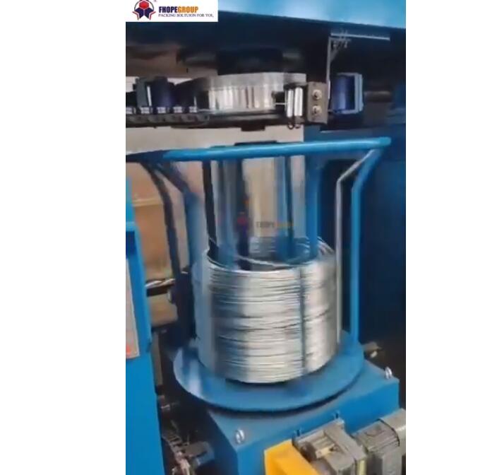
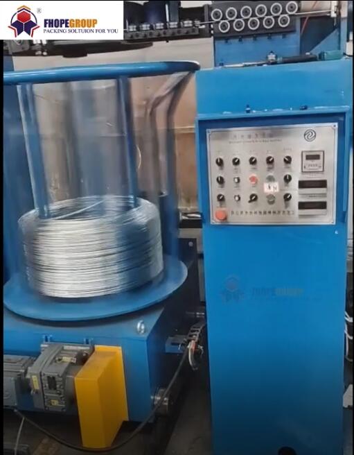
The machine has a heavy blue steel frame behind a blue safety fence. A yellow star-shaped coiling head sits on a geared motor, and yellow guide arms stand around it. A grey control cabinet with a row of push buttons and an emergency stop stands at the side.
- 0 to about 18 s. A coil of bright steel wire sits on the coiling head, seen through the fence. Nothing moves.
- About 24 to 42 s. The yellow holder lifts the coil, moves it and sets it down at the next station.
- About 48 to 54 s. A new wire end is led from the guide wheels onto the coiling head, and the guide arms close in.
- About 60 to 78 s. The head turns and the wire builds up in tight turns. Near the end, the wire is cut and the holder takes the coil.
- About 84 s. The finished coil rests at the unloading side, and the head is empty again.
- About 90 to 102 s. The machine stands still, with a wire coil on the yellow support.
- About 108 to 174 s. A second cycle runs. The wire is pulled in, the head turns faster, and the coil grows layer by layer.
- About 180 to 198 s. The holder comes down over the finished coil, grips it and lifts it off the head.
Cycle time on the clip
| Step on the clip | Time window | Duration |
|---|---|---|
| Coil lifted and moved by the holder | about 24 to 42 s | about 18 s |
| Wire end led onto the head | about 48 to 54 s | about 6 s |
| Winding to cut, first coil | about 60 to 78 s | about 18 s |
| Winding, second coil | about 108 to 174 s | about 66 s |
| Coil gripped and lifted off | about 180 to 198 s | about 18 s |
The times come from frames 6 s apart, and the clip may be edited. They show the order of steps, not a rated cycle time.
How the winding and strapping machine works
The wire first passes a meter counter. Its upper and lower wheels measure the length to the centimetre and send the signal to the cutter and the coiling head. A one-way bearing stops the wire from running back.
The coiling head moves up and down to take the wire end and fix it at the start. It opens and closes automatically, and a servo drive winds the wire into a regular coil shape. When the counter reaches the set length, the cutter cuts the wire.
A servo-driven holder then clamps the coil and carries it to the strapping station. There the coil is strapped through the eye, in 2 to 4 places, with PP strap joined by friction welding.
| Part | What it does |
|---|---|
| Meter counter | Measures wire length to the centimetre |
| Coiling head | Takes the wire end, winds the coil, opens to release |
| Automatic cutter | Cuts the wire at the set length |
| Servo holder | Clamps the coil and moves it to strapping |
| Eye-through strapper | Straps the coil in 2 to 4 places |
| PP strap pay-off | Stores strap and feeds it at the right speed |
Wire coil strapping data
| Strapping unit | Specification |
|---|---|
| Strap type | PP |
| Strap width | 8 to 10 mm |
| Strap thickness | 0.8 mm |
| Joint | Friction welding |
| Joint position | Front part of the wire coil |
| Joint strength | about 75 to 80% of the strap breaking load |
| Strap places | 2 to 4 per coil |
| Control | Touch screen, PLC and servo drives |
On the touch screen, the operator sets the winding speed, the wire length and the alarms. The coil size settings, wire length and wire diameter, can be changed on the screen while the machine runs.
Takt check
For an illustrative drawing line that finishes one coil every 120 s, the winding, cutting and holder transfer must all fit inside 120 s. On the clip, the second coil alone winds for about 66 s.
Where the strapper works on the previous coil while the next one winds, the slower of the two sets the pace. We then set the strap count to keep strapping below the winding time.
Selection checklist for a wire coil winder
- Wire diameter and grade.
- Coil length or weight, and the coil ID and OD.
- Line speed of the drawing machine.
- Strap places per coil, 2 to 4.
- Coil handling after strapping: conveyor, hook or pallet.
Controls and safety
On the clip, no one enters the fence while the head turns and the holder moves. The turning head, the cutter and the holder all move without warning, and a person inside the fence is the move to design out. We fence the cell and interlock the gates.
Stop, isolate and lock out the machine before anyone threads a new wire end, clears a tangle on the head or changes a strap coil. The emergency stop on the cabinet stops the head and holder at once.
The standards that apply depend on the destination market. For CE markets, ISO 12100 sets the risk-assessment method, and EN 415-10 covers general requirements for packaging machines, which fixes guarding and the stop arrangement.
Engineering FAQ
Q: How does the machine know when to cut the wire? A: A meter counter measures the wire to the centimetre, and the cutter acts when the set length is reached.
Q: How many straps go on each coil? A: Between 2 and 4, set in the program, with 8 to 10 mm PP strap.
Q: How strong is the strap joint? A: The friction-welded joint keeps about 75 to 80% of the strap breaking load.
Next step
We size a steel wire coil winding and strapping machine in three steps:
- Submit your layout drawing with the wire sizes, coil sizes and line speed, to info@fhopepack.com.
- Receive a proposal within 48 hours, with the coiler layout, the strap plan and the cycle check.
- Book a site survey so we confirm the drawing line, the floor space and the fenced cell.
Related reading
- Horizontal steel wire winding and strapping machine
- Automatic wire coiler
- Wire coil compacting and strapping
Sources
- Machine details and strap data: steel wire winding and strapping machine product page
- Clip timing: frame timings taken from the clip, 6 s between frames
- Machine in action: the video on YouTube
- Standards scope: ISO 12100:2010, EN 415-10:2014
Last reviewed: 2026-10-05