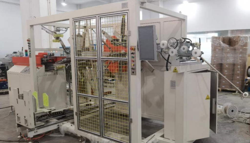
Executive summary Plasterboard edges crush easily under concentrated strapping tension, so board stacks are banded over timber battens rather than straight onto the gypsum board. The automated strapping machine stands ready with a board stack on its conveyor, timber strips staged on a side feeder, and a multi-joint placement arm positioned over the stack. Strap consumption and timber batten requirements per bundle follow directly from the bundle size and the number of bands. We calibrate both parameters per project.
Table of Contents
- Strapping station layout
- How the strapping station works
- Strap and batten use per bundle
- What we set per board size
- Controls and safety
- Selection checklist for a plasterboard strapping machine
- Engineering FAQ
- Next step
- Related reading
- Sources
Strapping station layout
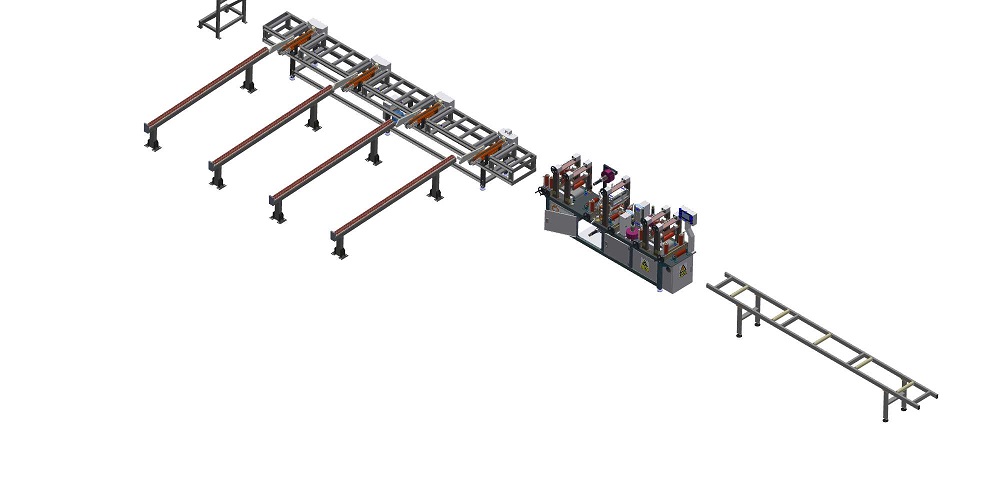
The automated plasterboard strapping station is engineered around an in-line heavy-duty roller conveyor that indexes board stacks directly into the strapping plane. Timber edge-protection battens are automatically staged on an integrated lateral feeder positioned to the side of the station.
An overhead multi-joint manipulator arm coordinates directly with the side magazine to pick and position timber battens across the top and bottom bundle edges at predetermined strap lines. Machine sequencing, indexing cycles, and strap tension recipes are managed through an industrial control cabinet equipped with physical operator pushbuttons, status indicator towers, and a dedicated digital interface for recipe recalls.
How the strapping station works
| Step | What happens |
|---|---|
| Feed | The board stack runs in on the conveyor |
| Timber | Battens come from the side feeder to the band positions |
| Place | The arm sets the battens at the band positions |
| Band | Straps go round the stack over the timber |
| Out | The banded bundle leaves the station |
Timber placed under the band spreads the concentrated strap load across the bundle surface, preventing the tensioned strap from cutting into or crushing the fragile plasterboard edges.
For integrated high-throughput lines, the automatic strapping station cycle time operates at ≤ 35–38 seconds per strapping cycle [manufacturer rating], which includes board stack indexing, timber positioning, strap feed, tensioning, and joint sealing.
Strap and batten use per bundle
Illustrative example:
| Item | Value |
|---|---|
| Bundle width (illustrative) | 1,200 mm |
| Bundle height (illustrative) | 400 mm |
| Band length, 2 × (1,200 + 400) | 3,200 mm |
| Bands per bundle (illustrative) | 4 |
| Strap per bundle before seal overlap, 4 × 3.2 m | 12.8 m |
| Battens per band (illustrative) | 2 |
| Battens per bundle, 4 × 2 | 8 |
Check the seal overlap on trial with your strap, since overlap length adds to every band applied. For automated plastic strapping systems, strap heads typically produce a friction-vibration weld with a joint efficiency rating of approximately 75–80% of the strap breaking load [manufacturer rating].
What we set per board size
| Setting | Why it matters |
|---|---|
| Band positions | Spaced along the board length |
| Batten length | Covers the bundle width |
| Band tension | Tight without crushing edges |
| Bundle height | Matches your forklift and truck |
Strapping heads feature adjustable tension control to match board density and stack stiffness. Depending on line requirements, machines accommodate PP or high-tensile PET strapping (e.g., 8–10 mm width × 0.8 mm thickness, or 12–13 mm width × 0.6–0.75 mm thickness) [manufacturer rating] to prevent surface abrasion while maintaining pack integrity.
We configure these parameters during factory acceptance trials using your specific board profiles and store them as permanent recipes in the control system. For timber bundling equipment, see our automatic lumber bundle strapping packing line.
Controls and safety
The mechanical arm moves continuously over the plasterboard stack and the strap is drawn under substantial tension during the cycling phase. Personnel must be kept outside the operating envelope while the station is energized and cycling; handling boards, adjusting timber magazines, or servicing strap coils must only be performed when the system is completely stopped and isolated.
The safety architecture and guarding standards depend on the destination plant’s regional regulations. For CE markets, ISO 12100 dictates the risk assessment and risk reduction methodology, while EN 415-10 specifies the harmonized safety requirements for packaging and strapping machines.
Selection checklist for a plasterboard strapping machine
- Board length, width and thickness.
- Bundle height and weight.
- Bands per bundle.
- Timber batten size.
- Bundles per hour.
- Conveyor height and line layout.
Engineering FAQ
Q: Why band over timber battens? A: The timber spreads the strap load over a wider surface area so the tensioned band cannot cut into or crush the friable plasterboard edges.
Q: How much strap does a bundle take? A: About 12.8 m for four bands on a 1,200 mm wide, 400 mm high bundle in our illustrative example, plus the seal overlap allowance required on each applied band.
Q: How many battens does a bundle need? A: 8 battens total, based on two battens per band with four bands applied per stack in our illustrative calculation.
Q: Where do the battens come from? A: An automated side conveyor feeder indexes and presents the timber battens directly to the placement arm.
Q: What is saved per board size? A: Band positions, batten length, band tension, and bundle height limits are stored as digital recipes in the PLC for rapid changeover.
Next step
We plan your plasterboard strapping machine in three steps:
- Submit your layout drawing with board sizes, bundles and output to info@fhopepack.com.
- Receive a proposal within 48 hours, with the band and timber plan.
- Book a site survey to check the conveyor layout.
Related reading
- Automatic strapping machines
- Video: gypsum board packaging line with orbital wrapper
- Video: wooden timber wrapping and strapping machine
Sources
- Automatic Plasterboard Packaging Line Specifications: FHOPE engineering team, 2026-10-04
- Strap and Batten Consumption Model: worked engineering example, illustrative values
- Harmonized Safety Standards: ISO 12100:2010, EN 415-10:2014
Last reviewed: 2026-10-29