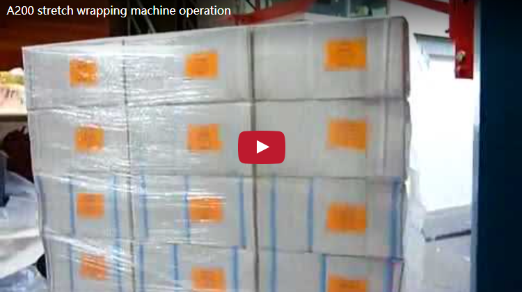
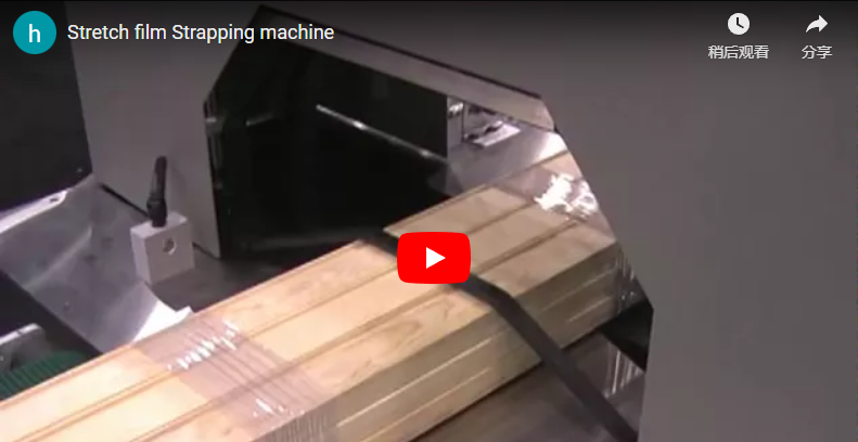
Executive summary The S200 horizontal orbital rod wrapping machine applies a high-tension spiral layer of LLDPE stretch film around single bars, structural rods, and narrow bundles as they advance through a rotating central ring bore. Integrated motor-driven V-conveyors automate continuous infeed and outfeed, while a handwheel-driven vertical lift carriage precisely aligns the centerline of workpieces measuring 10 to 200 mm in diameter with the orbital ring center. Engineered for payloads from 10 to 100 kg, the system synchronizes inverter-driven conveyor linear speed with ring rotation to maintain precise overlap ratios, eliminate surface scratching, and block transit corrosion. A complete engineering calculation below verifies film overlap dynamics, throughput cycle times, and structural payload boundaries.
Table of Contents
- Why wrap rods one by one
- How the rod passes through the ring
- Centring rods of different diameter
- S200 specifications
- Worked example: overlap, time and weight for a 100 mm rod
- Selection checklist: what to send us
- Safety and EN 415-10
- Engineering FAQ
- Next step
- Related reading
- Sources
Why wrap rods one by one
Finished round bars, polished shafts, and extruded aluminum or copper rods are highly vulnerable to abrasive surface scuffing, friction galling, and environmental oxidation when bundled loose or stacked directly on storage cantilever racks. A continuous, pressurized spiral wrap of high-performance stretch film seals each individual rod, forming a tight barrier against moisture, airborne dust, and metallic contact rub during warehouse handling and flatbed transit.
Manual bundle or spiral wrapping on extended bar stock exceeding 2,000 mm is labor-intensive, ergonomically hazardous, and prone to inconsistent film pre-stretch, leading to slack tails and exposed edges. The automated S200 orbital wrapper applies a uniform, calibrated spiral overlap along the full length of the workpiece at consistent conveyor line speeds, eliminating human error while cutting packing labor costs by over 70%.
How the rod passes through the ring
- Infeed Positioning: The bar or bundle is loaded onto the motorized infeed V-roller conveyor (2,000 mm standard bed), which axially feeds the product toward the rotating orbital housing.
- Optical Detection & Cycle Initiation: A high-response industrial photoelectric sensor array detects the leading edge of the rod, triggering automatic pneumatic top-press roller descent to stabilize the profile and initiating the orbital ring drive.
- Orbital Spiral Wrapping: The heavy-duty structural ring rotates around the advancing workpiece. A mechanical friction brake or dynamic pre-stretch carriage dispenses film under controlled tension (typically 15 to 40 N), laying a precise helical pattern across the circumference.
- Pneumatic Stabilization & Exit: Non-marking polyurethane outfeed pressure rollers maintain steady downward force on the trailing section, preventing workpiece whipping, axial slippage, or ring collision.
- Cut and Wipe: At the trailing edge, an operator severs the film, or an optional pneumatic cut-and-clamp unit cuts the web and wipes the film tail cleanly against the wrapped surface.
The S200 functions reliably as an autonomous, stand-alone workstation or easily integrates into continuous manufacturing lines downstream of polishing, extrusion, or cold-drawing cells.
Centring rods of different diameter
Workpieces varying between 10 mm and 200 mm in diameter have different physical centerline elevations when resting on a fixed horizontal conveyor. If the rod center deviates significantly from the rotational axis of the orbital ring, the film delivery web suffers from uneven trajectory lengths, resulting in excessive tension on one side and loose, billowing film on the opposing side.
To eliminate this dynamic imbalance, the S200 incorporates a heavy-duty, handwheel-operated vertical scissor lift carriage under the conveyor bed. The operator quickly adjusts the pass-line height according to an indexed scale, aligning the geometric center of any rod diameter directly with the ring rotational center.
Furthermore, dynamic ring stability is preserved through a dual-ring structural frame supported by paired polyurethane friction drive wheels and four precision perimeter guide rollers. This configuration absorbs radial runout and dampens rotational vibration even at maximum angular velocity.
S200 specifications
| Parameter / Specification | Standard S200 Base Rating | Optional / Custom Engineering |
|---|---|---|
| Workpiece length | ≥ 300 mm | Extended modular conveyor beds up to 12 m |
| Product outer diameter (OD) | 10–200 mm | Custom ring sizes for profiles up to 400 mm |
| Maximum product payload | 10–100 kg | Heavy-duty reinforced roller chassis up to 500 kg |
| Infeed conveyor length | 2,000 mm (motor-driven V-roller) | Custom lengths, automated kick-in table |
| Outfeed conveyor length | 2,000 mm (motor-driven V-roller) | Powered accumulation / ejection kick-off bins |
| Conveying linear feed speed | 4–12 m/min (VFD-regulated) | Synchronized closed-loop continuous pacing |
| Orbital ring rotational speed | 20–120 RPM (VFD-regulated) | Dual-inverter ramp acceleration control |
| Packaging material format | LLDPE stretch film (120–200 mm wide) | VCI anti-corrosion film, crepe paper, woven tape |
| Film roll outer diameter / core | Roll OD: 150–200 mm; Core ID: 50 mm (2 in) | Custom 76 mm (3 in) industrial core chucks |
| Installed electrical power | 2.1 kW, AC 380 V, 3-Phase, 50/60 Hz | Single-phase 220 V or 480 V industrial drops |
| Auxiliary options | Manual lever cut-off tool | Automated pneumatic clamp-and-cut system |
Worked example: overlap, time and weight for a 100 mm rod
To demonstrate kinematic calibration, consider a standard extrusion batch of solid 6061 aluminum alloy rods measuring 100 mm in diameter (D = 0.1 m) and 3,000 mm in length (L = 3.0 m), wrapped using a 150 mm wide film roll (W = 0.15 m).
1. Payload and Volume Assessment
The solid cylinder volume is: Volume = π × (D ÷ 2)² × L = π × (0.05 m)² × 3.0 m ≈ 0.02356 m³
- Aluminum Rod (Density ≈ 2,700 kg/m³): Weight = 0.02356 m³ × 2,700 kg/m³ ≈ 63.6 kg Result: 63.6 kg falls well within the S200 maximum 100 kg payload rating.
- Structural Steel Rod (Density ≈ 7,850 kg/m³): Weight = 0.02356 m³ × 7,850 kg/m³ ≈ 184.9 kg Result: Exceeds the standard S200 carriage limit (100 kg). Steel rods of this length require our heavy-duty S300 series reinforced chassis.
2. Film Overlap Kinematics at Full Ring Speed
The axial advance per ring revolution is governed by: Advance per turn = Film Width × (1 – Overlap Ratio)
At maximum orbital ring velocity (120 RPM), the infeed conveyor cannot exceed its structural top limit of 12 m/min (0.2 m/s). Therefore, the advance per turn must not exceed: Maximum Advance = (12 m/min) ÷ (120 rev/min) = 0.100 m = 100 mm per revolution
To achieve this, the minimum required overlap using 150 mm wide film is: Minimum Overlap = 1 – (100 mm ÷ 150 mm) = 33.3%
| Target Film Overlap (%) | Workpiece Advance per Turn (mm) | Infeed Conveyor Speed at 120 RPM (m/min) |
|---|---|---|
| 40% Overlap | 150 × (1 – 0.40) = 90 mm | 90 mm × 120 RPM ÷ 1,000 = 10.8 m/min |
| 50% Overlap | 150 × (1 – 0.50) = 75 mm | 75 mm × 120 RPM ÷ 1,000 = 9.0 m/min |
| 60% Overlap | 150 × (1 – 0.60) = 60 mm | 60 mm × 120 RPM ÷ 1,000 = 7.2 m/min |
3. Lower Ring Speed Boundary
Because the motor conveyor variable frequency drive has a minimum continuous torque cut-off at 4.0 m/min, operating the ring too slowly causes gaps in coverage. At the absolute minimum ring speed of 20 RPM, advance per turn would reach 4,000 mm ÷ 20 = 200 mm, exceeding the 150 mm film width and leaving unwrapped metal. To maintain a safe 50% overlap (75 mm advance per turn) at minimum conveyor feed (4.0 m/min), the ring must run at: Minimum Ring Speed = 4,000 mm/min ÷ 75 mm/rev = 53.3 RPM Our synchronized dual-VFD panel links conveyor forward drive directly to ring tachometer feedback to prevent pitch errors during line ramping.
4. Cycle Time and Material Consumption
At a balanced 50% overlap (advance = 75 mm/rev, conveyor speed = 9.0 m/min):
- Net Wrapping Time: 3.0 m ÷ 9.0 m/min = 0.333 min = 20.0 seconds per rod.
- Ring Revolutions: 3,000 mm ÷ 75 mm/rev = 40 full rotations.
- Film Consumption per Turn: Circumference = π × D = π × 0.10 m = 0.3142 m Helical Length per Turn = √((Circumference)² + (Advance)²) = √((0.3142)² + (0.075)²) ≈ 0.323 m
- Total Film per Bar: 40 turns × 0.323 m ≈ 12.92 linear meters (prior to mechanical pre-stretch elongation).
Selection checklist: what to send us
To ensure exact mechanical integration and conveyor sizing, provide our packaging engineering group with the following production data:
- Workpiece Outer Dimensions: Minimum and maximum cross-sectional diameters (OD) or bundle cross-sections (W × H in mm).
- Length Spectrum: Minimum and maximum cut lengths (mm) to calculate roller pitch and bridge transitions.
- Mass Profiles: Minimum and maximum unit weights (kg/piece or kg/meter) and base metallurgy (aluminum, copper, stainless steel, alloy tool steel).
- Surface Quality Class: Mirror-polished, ground, pickled, or primed finishes requiring vulcanized non-marking polyurethane V-rollers.
- Target Line Throughput: Required parts per hour or linear meters per minute to determine automation level (manual feed vs. automated inline transfer).
- Facility Utilities: Nominal plant power supply (e.g., 230 V / 400 V / 480 V, 50/60 Hz) and plant compressed air availability (0.5–0.7 MPa for pneumatic clamping).
Safety and EN 415-10
The S200 is designed and CE-certified in strict compliance with EN 415-10 (Safety of Packaging Machines – Part 10: General Requirements) and verified via ISO 12100:2010 comprehensive risk assessment protocols.
Key mechanical safety provisions include:
- Hazard Containment: Heavy-gauge perimeter steel tunneling covers the rotating ring chassis and high-speed film carriage, mitigating pinch hazards and projectile risks in the event of film core failure.
- Infeed/Outfeed Safety Clearances: Mechanical tunnel extensions safeguard pinch points adjacent to descending vertical pressure rollers.
- Fault Annunciation & E-Stop Architecture: Dual-channel Category 3 / PL d emergency stop circuits immediately trip the main dynamic braking resistor, decelerating the orbital ring to a complete standstill in under 1.5 seconds.
- Visual Diagnostics: A multi-tier status beacon with audible alarm provides real-time diagnostic reporting for film runout, thermal overload, and photocell misalignment.
Engineering FAQ
Q: Can the S200 wrap hex bars, square profiles, and small multi-piece bundles? A: Yes. As long as the maximum circumscribed diagonal cross-section does not exceed 200 mm and total unit weight stays within 100 kg, non-round stock and pre-bundled groups wrap securely without manual pre-binding.
Q: How does the system interface with an automated continuous production line? A: The standard S200 control enclosure features an industrial PLC with dry contacts and auxiliary fieldbus ports. It easily exchanges handshake signals (Ready to Receive, In-Cycle, Feed Complete, Alarm Interlock) with upstream sawing cells or downstream bundling stackers.
Q: Can we run corrosion-inhibiting paper or heavy reinforced tape instead of standard LLDPE film? A: Yes. The modular film mandrel accepts VCI polyethylene film, crepe kraft paper, and reinforced woven polypropylene rolls with standard 50 mm (2 in) or optional 76 mm (3 in) internal cores.
Q: What preventive maintenance is required on the rotational drive? A: Routine maintenance is minimal: inspect and grease the primary guide roller bearings every 1,000 operating hours, check tension on the flat ring drive belt, and clean accumulated film dust from the photocell lenses weekly.
Next step
- Email Your Specifications: Forward your diameter ranges, length variations, target line speeds, and material grades to info@fhopepack.com.
- Receive Technical Proposal: Our application engineering team delivers an engineering proposal within 24 hours, specifying exact drive ratios, conveyor lengths, and film roll specifications.
- Review 2D/3D Layouts: We provide project-specific CAD line integration and floor-loading footprints for plant engineering approval.
Related reading
- Semiauto horizontal orbital wrapper S200
- Automatic bar wrapping machine
- Aluminum rod material wrapper
- Copper sheet and bronze bar wrapping machine
Sources
- Machine Engineering Data: FHOPE S200 Semiauto Horizontal Orbital Wrapper Technical Specifications
- Video Demonstration: FHOPE Industrial Rod and Bar Wrapping System Demonstration
- Kinematics & Overlap Models: Internal OEM Packaging Calculation Standards for Orbital Spiral Winders
- Regulatory Directives: EN 415-10 (Safety of Packaging Machines – General Requirements); EN ISO 12100:2010 (Safety of Machinery – General Principles for Design)
Last reviewed: 2026-10-17