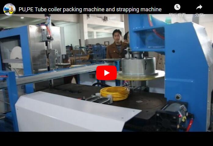
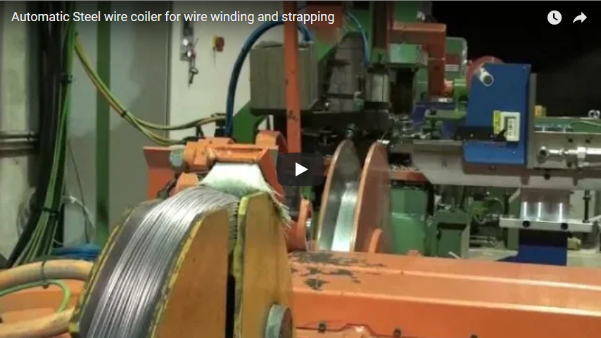
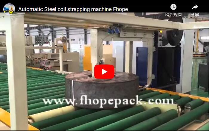
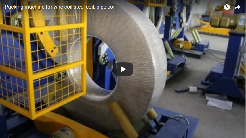
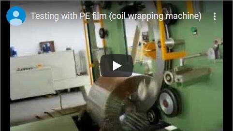
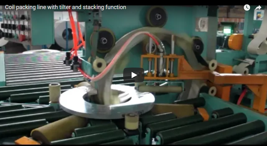
Executive Summary An automated slit coil strapping, wrapping, and stacking line synchronizes coil downending, precision indexing, radial through-the-eye strapping, orbital stretch wrapping, and robotic pallet stacking into a continuous material flow. Engineered specifically for narrow-width steel, aluminum, and copper slit coils in an eye-to-sky (axis-vertical) orientation, this architecture eliminates overhead crane bottlenecks, prevents telescoping and edge damage, and maintains tight line cycle times (60–90 seconds per coil). This engineering guide details station kinematics, material sizing calculations, safety standards, and factory floor integration requirements.
Why Slit Coils Demand Dedicated Packaging Lines
Slit coils processed from master coils present distinct handling hazards compared to wide-strip master coils. Because narrow slit strips feature high aspect ratios (narrow width relative to large outer diameter), they exhibit extreme lateral instability:
- Telescoping and Edge Burrs: Loose outer wraps easily shift under side loads, leading to permanent strip edge deformation and coil unraveling.
- Surface Scratching: Coated, galvanized, or automotive-grade slit surfaces are susceptible to strap bite and friction marks if handled with manual chains or steel c-hooks.
- Production Bottlenecks: High-speed slitting heads produce 10 to 30 slit mults per master coil. Transporting and banding each coil individually via forklift creates severe line congestion.
A dedicated packaging system transitions slit coils directly from the slitter exit recoiler car onto powered roller conveyors, automating securement without intermediate manual transfers.
Industrial End-Use Requirements
Automated slit packaging lines support varied strip metallurgies and processing demands:
- Automotive Stamping: Requires clean, dent-free edges and corrosion-inhibiting (VCI) film wraps without residual oil contamination.
- Building and Construction (Purlins, Decking): Demands heavy-gauge steel strapping (up to 32 mm) to withstand harsh flatbed transit.
- Electrical Transformers and Appliances: Requires silicon steel and non-ferrous strip processing with strict mechanical clamp pressure limits to avoid core loss and edge stress.
A single integrated packaging line handles these diverse specifications by electronically adjusting strap tension parameters, wrapping pre-stretch ratios, and stacking sequences via master PLC recipes.
System Architecture: Station-by-Station Operation
The complete packing line coordinates five sequential operating stations, using automated buffer zones to isolate machine cycles.
[Slitter Recoil Turnstile]
       │
       ▼
[Station 1: 90° Hydraulic Downender & Centering Conveyor]
       │
       ▼
[Station 2: Inner-Layer Protective VCI / Crepe Paper Wrapping]
       │
       ▼
[Station 3: Automatic Radial (Through-the-Eye) Strapping]
       │
       ▼
[Station 4: High-Speed Orbital Stretch Wrapping]
       │
       ▼
[Station 5: Automated Stacking, Dunnage Placement & Palletizing]
Station 1 — Coil Infeed, Downending, and Centering
Coils typically leave the slitting arbor eye-horizontal on an exit turnstile.
- Downending: A heavy-duty electro-hydraulic tilter cradles the individual coil and downends it 90°, setting it flat into an eye-to-sky (axis-vertical) position.
- Conveyor Infeed: The coil shifts onto heavy-walled, polyurethane-sleeved powered rollers.
- Centering Table: Centering rollers align the coil bore (ID) precisely to the conveyor centerline, establishing an exact mechanical datum for downstream strapping heads and stacker grippers.
| Parameter | Standard Industrial Range | Heavy-Gauge Line Range |
|---|---|---|
| Coil Outer Diameter (OD) | 600 – 1,500 mm | Up to 2,000 mm |
| Coil Inner Diameter (ID) | 400 – 762 mm | 508 – 610 mm |
| Slit Strip Width | 20 – 500 mm | Up to 800 mm |
| Coil Weight Range | 200 – 4,000 kg | Up to 6,000 kg |
| Roller Conveyor Speed | 8 – 25 m/min (VFD controlled) | 8 – 20 m/min |
Station 2 — Inner-Layer Wrap (Corrosion and Surface Barrier)
Before high-tension strapping, an internal protective layer is applied around the coil ring. A dedicated orbital shuttle dispenses VCI film, crepe paper, or reinforced HDPE tape through the coil bore. This layer:
- Guards internal wraps against moisture ingress and condensation staining.
- Creates a protective buffer that prevents high-tension steel or PET strap edges from scoring the outer metal layers.
- Provides color-coded identification for distinct strip alloys and production heats.
Station 3 — Automatic Radial Steel / PET Strapping
This station applies high-tension radial straps through the coil eye. The coil is positioned on a motorized indexing turntable.
- A segmented strap track (strap lance) extends downwards through the open bore.
- The strapping head feeds, tensions, cuts, and joins the strap.
- The turntable rotates 90° or 120°, and the cycle repeats to apply 2, 3, or 4 radial straps per coil.
                  [Coil Bore (ID)]
                  ┌──────────────┐
                  │              │
    ◄─────────────┼── Strap Path ┼─────────────►
                  │  (Through    │
                  │   the Eye)   │
                  │              │
                  └──────────────┘
The required strap feed length (L_strap) accounts for the rectangular coil cross-section plus mechanical joint and feed clearances:
T_wall = (OD - ID) / 2
L_strap = (2 × Width) + (2 × T_wall) + C_clearance + L_joint
Where:
T_wall: Radial wall thickness of the slit coil.C_clearance: Physical strap chute clearance (typically 150 – 250 mm based on lance stroke).L_joint: Strap lap allowance consumed in the sealer head (60 – 90 mm).
Worked Example: For a slit coil with Width = 150 mm, OD = 1,200 mm, and ID = 508 mm:
T_wall = (1,200 - 508) / 2 = 346 mm- Theoretical perimeter =
(2 × 150) + (2 × 346) = 992 mm - With
C_clearance = 200 mmandL_joint = 80 mm, the machine strap feed is programmed for 1,272 mm.
| Strapping Machine Specification | Standard Capability |
|---|---|
| Compatible Strap Types | High-tensile steel, heavy-duty embossed PET |
| Strap Widths | 16 mm, 19 mm, 32 mm |
| Strap Thickness | 0.50 – 0.90 mm |
| Tension Range (Steel) | 2,500 – 6,500 N (continuously adjustable) |
| Strapping Cycle Time | 12 – 18 seconds per radial strap |
Station 4 — High-Speed Orbital Stretch Wrapping
Once strapped, the coil moves into an orbital wrapping ring to receive a moisture- and dust-tight outer shell.
- The coil sits on conical support rollers that rotate it continuously around its vertical center axis.
- A high-speed rotating ring carries a film dispenser carriage through the coil bore.
- The machine applies a 360° helical wrap of stretch film (LLDPE) combined with paper or woven composite tape.
- Electronic pre-stretch carriages elongate the stretch film up to 250% – 300%, significantly increasing holding tension while cutting film consumption.
Station 5 — Automated Pick-and-Place Pallet Stacking
The wrapped slit coil advances to the stacker station. Depending on coil weight and strip finish, stacking is performed by:
- Gantry-Mounted Scissor Grippers: Dual mechanical arms grab the coil OD or ID safely using urethane-padded pads.
- Overhead Vacuum Lifter: Ideal for flat-faced, dry steel sheets where side clamps risk scratching edges.
The stacker transfers each coil onto a wooden pallet. In high-specification operations, an integrated dunnage magazine automatically lays 3 to 4 radial wooden or plastic spacers between stacked coils. This permits C-hook or fork tine access at downstream customer plants.
The total payload supported by the pallet and stacker elevator:
W_stack = (N_coils × W_coil) + W_dunnage + W_pallet
Worked Example: Stacking 4 slit mults weighing 750 kg each on a 40 kg hardwood pallet with 15 kg total dunnage:
W_stack = (4 × 750) + 15 + 40 = 3,055 kgThe hydraulic/servo stacker lifting mechanism and pallet delivery conveyor must be rated for a safe working load (SWL) of at least 3,500 kg.
Technical Comparison: Packaging Consumables
| Property / Parameter | High-Tensile Steel Strap | Embossed PET Strap | LLDPE Stretch Film Wrap |
|---|---|---|---|
| Primary Engineering Function | Internal radial bundle integrity | Tension shock absorption; non-rust | Environmental seal, rust and dust proofing |
| Tensile Strength / Break Load | 12,000 – 25,000 N (19–32 mm) | 7,000 – 11,000 N (19 mm) | 25 – 40 MPa yield strength |
| Elongation at Break | 6% – 12% | 12% – 16% | 200% – 300% (pre-stretched) |
| Surface Scratch Hazard | Moderate to High (requires corner pads) | Low (soft polymer edge) | Zero (non-abrasive) |
| Best-Fit Applications | Heavy export sea freight, thick hot-rolled slit strips | Domestic road transit, stainless steel, aluminum | Final full wrap for all metal grades |
Pallet Stacking Architecture and Floor Stability Limits
Stacking height and configuration must respect mechanical stability parameters to ensure safe logistics handling:
Multi-Tier Eye-to-Sky Stack:
   ┌───────────────────────┐ ◄── Top Slit Coil
   │  ===================  │ ◄── Radial Wooden Dunnage
   ├───────────────────────┤ ◄── Middle Slit Coil
   │  ===================  │ ◄── Radial Wooden Dunnage
   ├───────────────────────┤ ◄── Base Slit Coil
   └───────────────────────┘
═════════════════════════ ◄── Heavy-Duty Pallet- Stack Height Ratio (Aspect Stability):
Total stack height (
H_stack) must not exceed the minimum outer diameter of the coil base:H_stack ≤ 1.2 × OD_minExceeding this ratio introduces tip-over risks during forklift turning acceleration. - Center of Gravity Maintenance:
The stacker’s optical centering system ensures concentric stack alignment within
±3 mm. Eccentric stacking creates point loads that shatter standard pallet skids during warehousing rack placement.
Line Control Architecture and Machine Safety Standards
Automated high-speed coil movement involves high mechanical inertia. The line incorporates strict safety automation in compliance with international machinery directives:
- PLC Control System: Centralized Siemens S7-1500 or Allen-Bradley GuardLogix master controller communicating across high-speed PROFINET / EtherNet/IP networks.
- Safety Light Curtains & Fencing: Guard zones protect the downender, radial strapping machine, and gantry stacker in compliance with ISO 12100 (Risk Assessment) and EN 415-10 (Packaging Machine Safety).
- Interlocked Station Zoning: Dual-channel safety gate switches shut down hazardous pneumatic, hydraulic, and motor actuators instantly via zoned Category 4 / PLe safety relays.
- Safe Torque Off (STO) & Lock-Out/Tag-Out (LOTO): All drives feature hardware-level STO, with pneumatic/hydraulic dumps integrated for safe mold, blade, and strap roll servicing.
Factory Layout Footprint Planning
Floor planning depends directly on intermediate buffer capacities and slitter exit configurations:
| Section Description | Minimum Required Length | Clear Width Required | Functional Purpose |
|---|---|---|---|
| Infeed Conveyor & Tilter | 4.0 – 6.0 m | 2.5 – 3.0 m | Downending and inline weight checking |
| Pre-Wrap & Centering Station | 3.0 – 4.0 m | 2.5 – 3.0 m | ID centering and edge/barrier layer application |
| Radial Strapping Machine | 3.5 – 4.5 m | 3.0 – 3.5 m | Turntable rotation and radial band placement |
| Orbital Stretch Wrapper | 3.5 – 5.0 m | 3.0 – 3.5 m | Through-eye film encapsulation |
| Robotic Stacker & Palletizer | 5.0 – 7.0 m | 4.0 – 5.0 m | Coil picking, dunnage insert, pallet discharge |
| Total System Envelope | 19.0 – 26.5 m | 4.0 – 5.0 m | Continuous, uninhibited linear workflow |
Performance Analysis: Manual vs. Automated Processing
| Production Variable | Conventional Manual Packaging | Automated FHOPE Line | Production Impact |
|---|---|---|---|
| Line Output | 8 – 15 coils/hour | 45 – 90 coils/hour | Up to 5× increase in throughput |
| Direct Labor per Shift | 4 – 6 operators | 1 operator (monitoring/replenishment) | Direct payroll savings of 75% |
| Edge Damage / Scrap Rate | 2.5% – 5.0% | < 0.2% | Substantial raw material cost recovery |
| Strap Tension Accuracy | Variable (manual torque) | ±3% of programmed N | Eliminates sea-transit bundle loosening |
| Crane & Forklift Use | Continuous (high risk) | Confined strictly to pallet outfeed | Frees overhead crane time for slitting |
| System Payback (ROI) | N/A | 8 – 14 months | Rapid break-even on 2-shift operations |
Engineering FAQ
Q: How does the line compensate for oily or slippery cold-rolled slit coils?
A: Rollers are fitted with high-friction vulcanized polyurethane sleeves, and clamp tables use knurled pneumatic stabilizing pads. Additionally, the radial strap tension sequence uses gradual ramp-up profiles to seat straps firmly without inducing lateral coil wrap displacement.
Q: Can different coil widths run on the line without mechanical retooling?
A: Yes. All machine components—centering arms, orbital wrapper shuttles, and stacker gripping heads—operate on closed-loop servo drives with laser distance sensors. Changeovers between 30 mm and 500 mm strip widths take place instantly via automated PLC recipe selection.
Q: What is the minimum coil ID the strapping lance can clear?
A: Standard radial strapping lances require a minimum coil inner diameter of 400 mm. For ultra-narrow applications, low-profile compact lances can be custom-engineered to clear a minimum ID of 300 mm.
Q: Does the line support automatic dunnage (wooden spacer) placement?
A: Yes. A dedicated vacuum or pneumatic gripper dunnage magazine can be integrated directly onto the gantry stacker arm to place three radial wooden laths onto the coil face before descending the subsequent coil.
Project Specification and RFQ Checklist
To size your automated packaging line layout and receive an optimized engineering layout, prepare the following parameters for our technical team:
- Slit Strip Dimensions: Minimum and maximum slit widths (mm), min/max coil OD and ID (mm).
- Coil Weight Profile: Minimum and maximum coil weights (kg), maximum allowable pallet load.
- Line Speed Requirements: Output of slitting line (coils per hour or shifts per day).
- Packaging Specification: Preferred strapping material (Steel/PET), strap count (2, 3, or 4 radial bands), and film layer configuration (VCI, LLDPE, or woven tape).
- Stacking Profile: Target coils per stack, pallet dimensions (wooden skid or standard pallet), and interlayer dunnage requirements.
- Facility Envelope: Available installation length, width, ceiling hook clearance, and main power/air supply parameters.
Contact Our Engineering Department: Submit your layout parameters to our application engineers at info@fhopepack.com for a customized 3D layout simulation and quotation within 48 business hours.